M3plus_OperationManual_e.pdf - 第123页
3 - 58 3 Creating the PCB data 4. Creating the component information N, O: WastedSpace Left, Light When a TSF1 is installed on the feeder plate, these parameters define the feeder set positions where 8mm tape feeders can…
3 -57
4. Creating the component information
3
Creating the PCB data
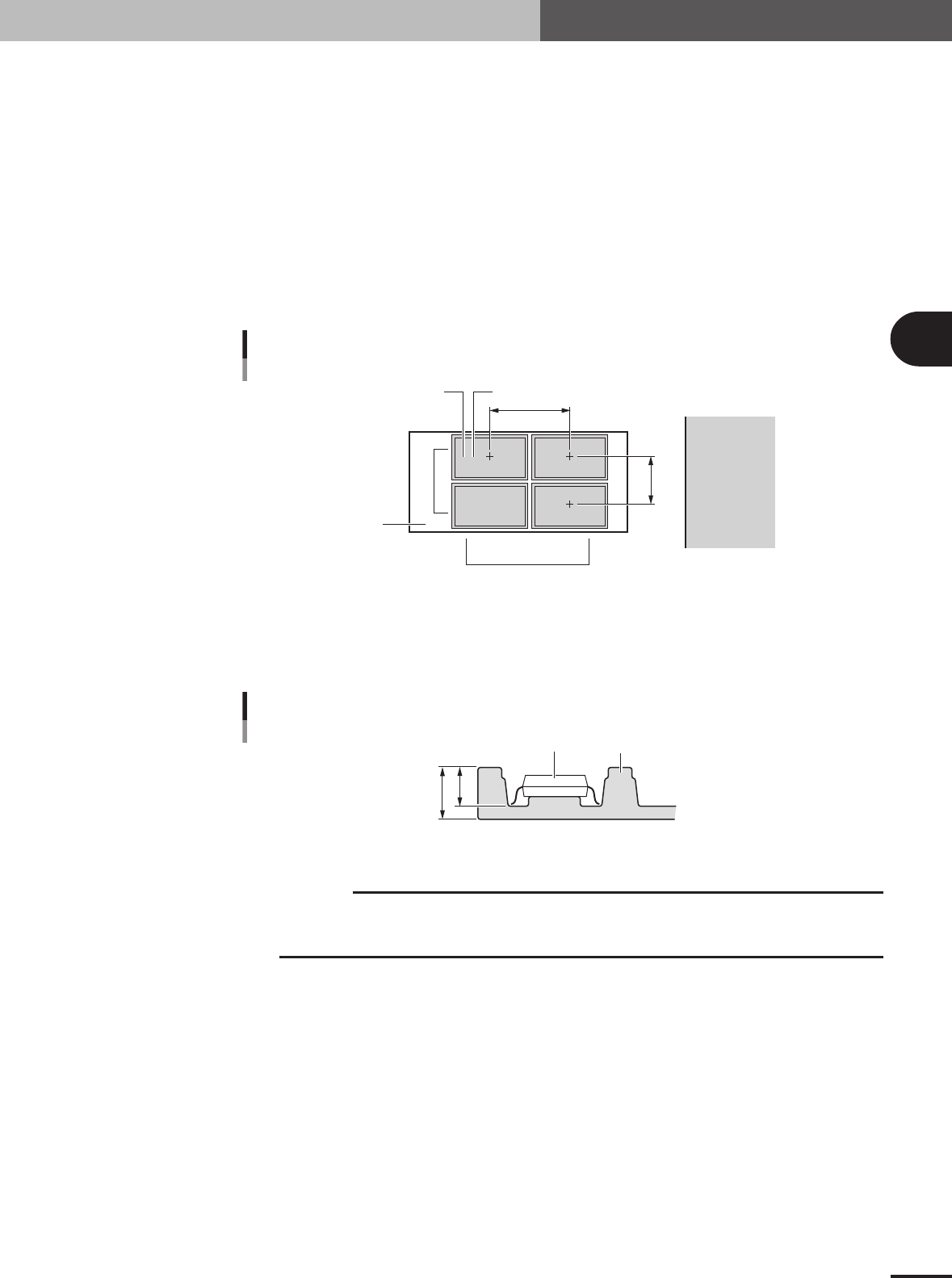
G, H: Tray Amount XY
These parameters specify the number of trays set in the XY directions on the shuttle. For example
in the figure below, enter "2" for the Tray Amount X parameter, and "2" for the Tray Amount Y
parameter.
I, J: Tray Pitch XY
These parameters set the center to center spacing of the adjacent trays. When only one tray is set
on the shuttle, both the Tray Pitch X and Tray Pitch Y parameters should be "0.00".
K, L: Current Tray XY
These parameters indicate which row and column on the shuttle the tray is currently used. Nor-
mally, enter "1" for both Current Tray X and Current Tray Y parameters. With these parameters set
to "1", the machine starts picking up a component from the tray placed closest to the tray reference
position.
2,1 1,1
2,2 1,2
Tray Amount / Tray Pitch settings
G
H
J
I
LK
Shuttle
Feeder side
23433-5E-20
M: Tray Height
Enter the thickness (mm) of the tray by referring to the figure below. The sum of the "Body Size
Z" and the value you entered here determines the component pickup height, so measure the tray
thickness correctly.
B
A
Component
Tray
Tray height (thickness) = A – B
Tray height (thickness)
23445-5E-20
c
CAUTION
The "Height" parameter is set to "0" by default. Be sure to enter the correct tray thickness to
prevent the nozzle from pushing the component too far. Failure to do so might cause pickup
errors or damage to the nozzle and head.
3 -58
3
Creating the PCB data
4. Creating the component information
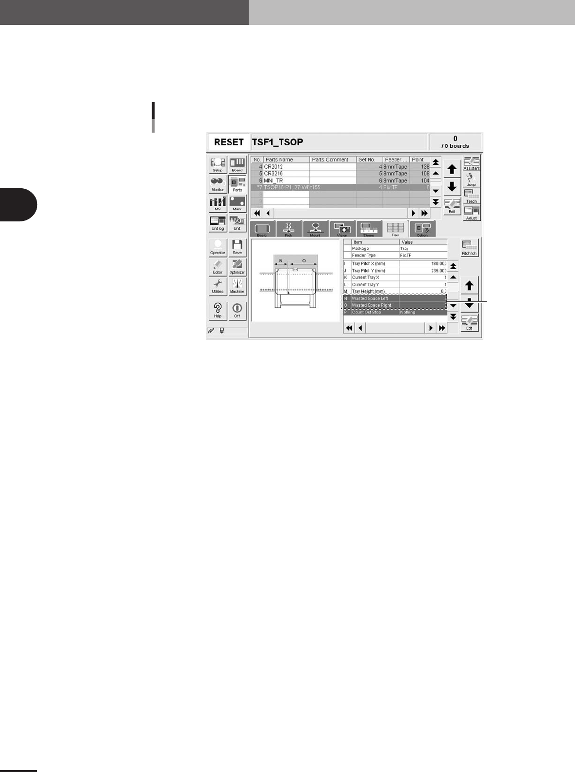
N, O: WastedSpace Left, Light
When a TSF1 is installed on the feeder plate, these parameters define the feeder set positions
where 8mm tape feeders cannot be attached to the feeder plate. These parameters should be set
with the Feeder No. specified in Step 5 as the reference. In the case of the TSF1, enter "3" in the
"WastedSpace Right" and WastedSpace Left" parameter fields.
WastedSpace Left, Light
TSF1
Set these
parameters.
27319-5E-20
P: CountOutStop
When this parameter is set to "Exist", the machine automatically stops when the specified number
of components is used up. When set to "Nothing", the machine returns to the first position to
continue component pickup after the specified number of components is used up. Normally set this
parameter to "Nothing".
3
Creating the PCB data
3 -59
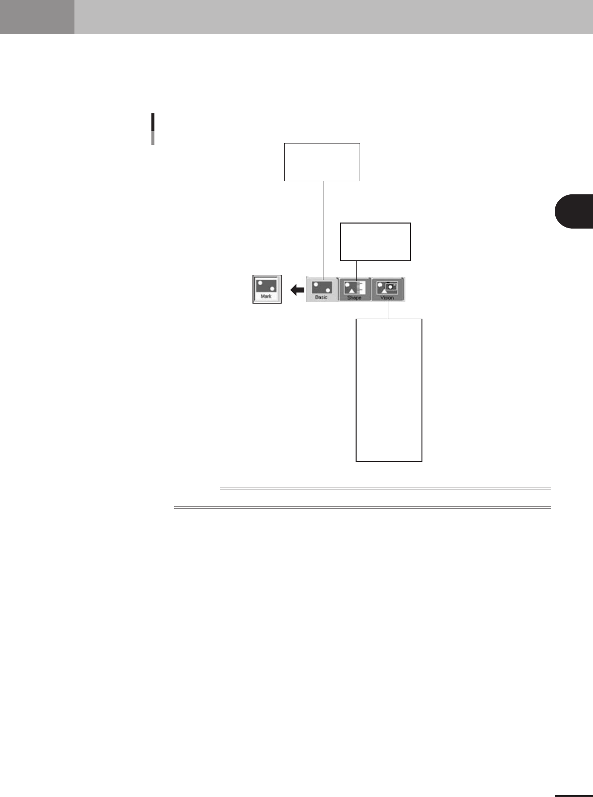
5. Creating the mark information
This section describes how to create mark information for fiducial marks used on a PCB. Mark infor-
mation has various parameters for each of the mark names registered. To set these parameters, copy
sample data of a mark with a similar shape from the database and edit only the different parameters.
Optimal parameter values can also be found by making checks and adjustments in Mark Adjust mode.
Mark information parameter
Mark Name
Mark Comment
(Mark Type)
Shape Type
Mark Out Size
etc.
Surface Type
Algorithm Type
Mark Threshold
To lerance
Search Area X
Outer Light
Inner Light
Coaxial Light
IR Outer Light
IR Inner Light
Cut Outer Noise
Cut inner Noise
Sequence
Mark Type
Database Number
(Library Name)
23438-5E-20
Reference
Parameters displayed somewhat differ depending on the selected "Mark Type" or "Shape Type".