M3plus_OperationManual_e.pdf - 第125页
3 - 60 3 Creating the PCB data 5. Creating the mark information 5.1 Creating procedure Pressing the Mark button in the menu button area opens the mark information screen as shown below. Enter the mark name and comment in…
3
Creating the PCB data
3 -59
5. Creating the mark information
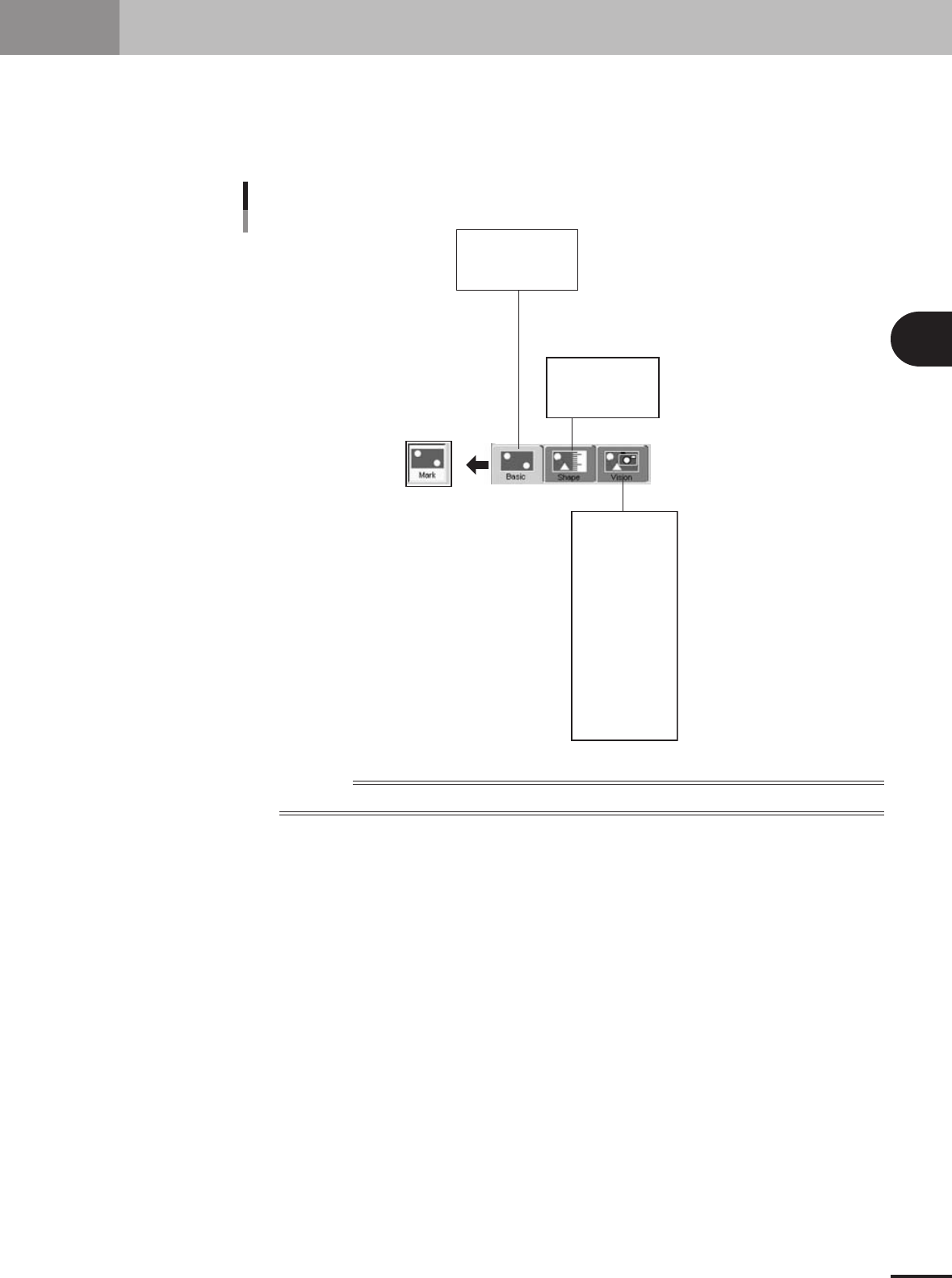
This section describes how to create mark information for fiducial marks used on a PCB. Mark infor-
mation has various parameters for each of the mark names registered. To set these parameters, copy
sample data of a mark with a similar shape from the database and edit only the different parameters.
Optimal parameter values can also be found by making checks and adjustments in Mark Adjust mode.
Mark information parameter
Mark Name
Mark Comment
(Mark Type)
Shape Type
Mark Out Size
etc.
Surface Type
Algorithm Type
Mark Threshold
To lerance
Search Area X
Outer Light
Inner Light
Coaxial Light
IR Outer Light
IR Inner Light
Cut Outer Noise
Cut inner Noise
Sequence
Mark Type
Database Number
(Library Name)
23438-5E-20
Reference
Parameters displayed somewhat differ depending on the selected "Mark Type" or "Shape Type".
3 -60
3
Creating the PCB data
5. Creating the mark information
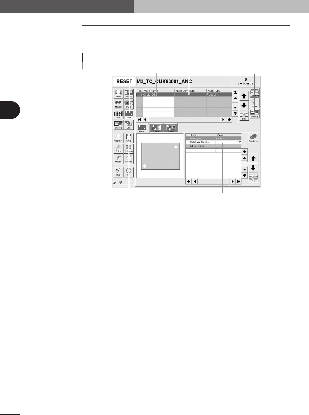
5.1 Creating procedure
Pressing the Mark button in the menu button area opens the mark information screen as
shown below. Enter the mark name and comment in the upper grid of the screen, and set
the parameters in the right lower grid, as explained below.
Step 2Step 1 Step 3
Step 5
Step 4Step 7
Mark information screen
27202-5E-2A
1
Press the [Mark] button to open the mark information screen.
2
Enter the mark name in the Mark Name column.
Enter a different name for each mark within 20 alphanumeric characters. A space
cannot be included in the name.
3
Enter a comment.
Type any desired comment in the Mark Comment column as necessary. You can omit
entering comments here.
4
Set the parameters.
While selecting the [Basic], [Shape], [Vision] tabs and so forth, set the necessary
parameters in the right lower list.
5
Adjust the parameters in the Parts Adjust mode.
Press the [Adjust] button to open the Parts Adjust screen that allows you to adjust or
check the parameters of the selected component. (For more details, see "5.5 Mark
Adjust mode" in this chapter.)
6
Repeat the above steps for other marks.
Repeat the same procedure from step 2 to register all marks to be used.
7
Save the data.
Press the [Save] button to store the data.
3 -61
3
Creating the PCB data
5. Creating the mark information
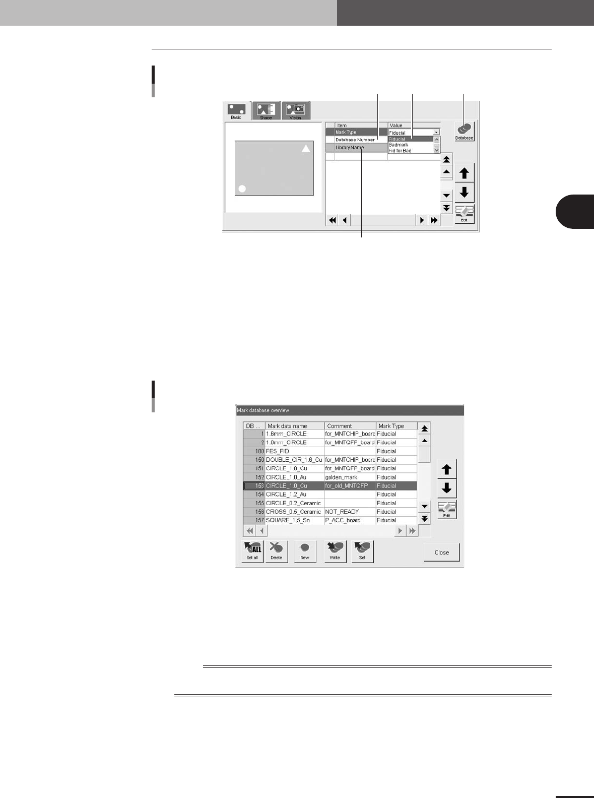
5.2 Basic parameters
[Database] button
21
3
Basic parameters
27445-5E-20
1 Mark Type
Select the mark type from the dropdown list. Select "Fiducial" when using a fiducial mark, and select
"Badmark" when using a badmark. If using a fiducial mark as a badmark, select "Fid for Bad". The
item selected here will be displayed on the Mark Type column in the data No. list.
2 Database Number
Shows the database number when the parameter values were copied from the database.
When you want to copy the parameter values from the database, press the [Database] button to open
the database list. Then select the copy source data and press the [Set] button to make a copy.
Database list
27446-5E-20
3 Library Name
Shows the component data library name when used.
To check the library link setting (library file path), place the cursor on "Library Name" and press the
[Edit] button.
n
NOTE
For details on the library setting, see "3. Creating XML library" in chapter 6. To use the library function, PCB
data must be saved in XML format.