M3plus_OperationManual_e.pdf - 第127页
3 - 62 3 Creating the PCB data 5. Creating the mark information 5.3 Shape parameters Shape parameters 27447-5E-20 Shape Type The Shape Type can be selected from the following 5 types. Setting Description Example Circle S…
3 -61
3
Creating the PCB data
5. Creating the mark information
5.2 Basic parameters
[Database] button
21
3
Basic parameters
27445-5E-20
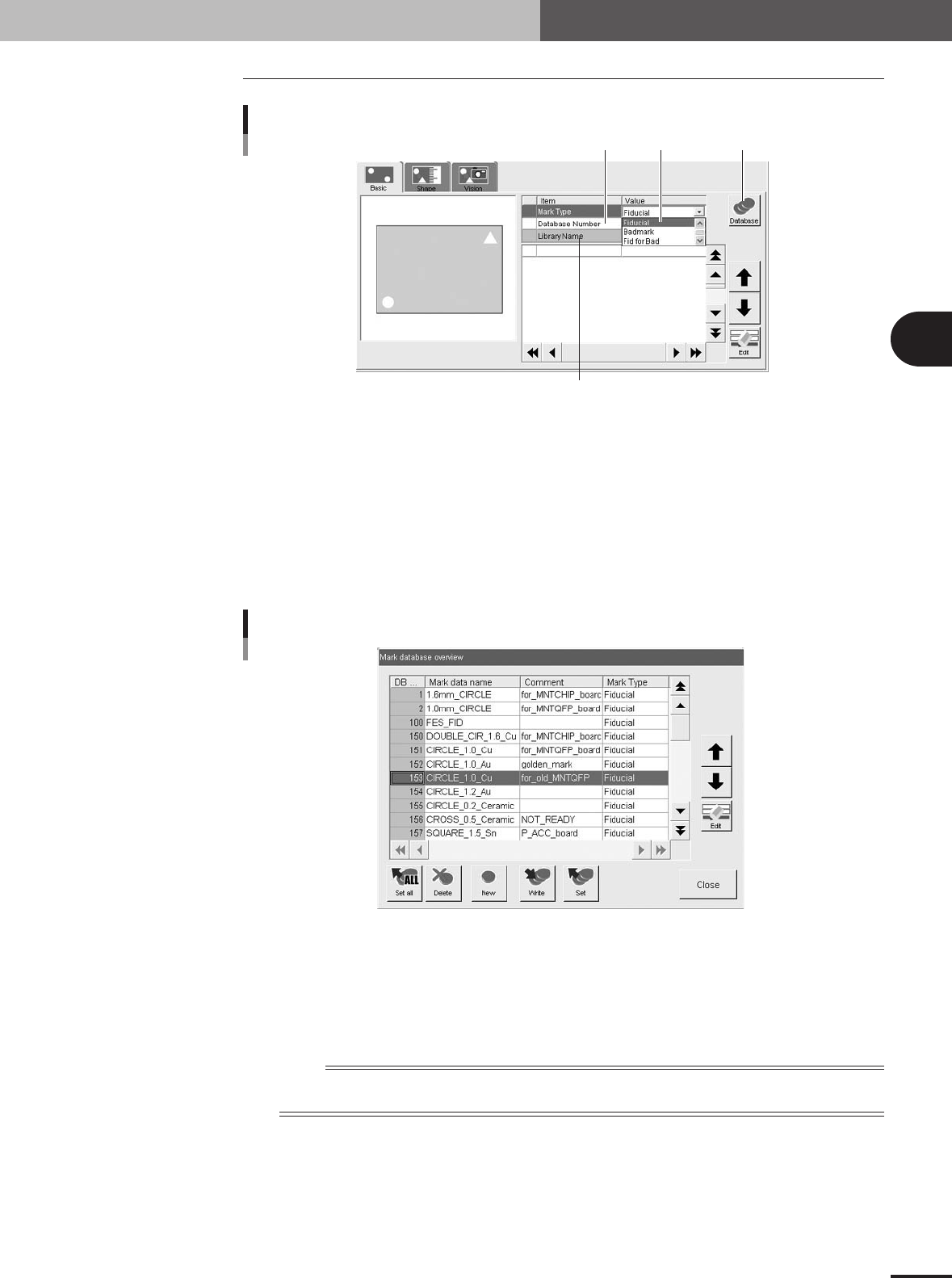
1 Mark Type
Select the mark type from the dropdown list. Select "Fiducial" when using a fiducial mark, and select
"Badmark" when using a badmark. If using a fiducial mark as a badmark, select "Fid for Bad". The
item selected here will be displayed on the Mark Type column in the data No. list.
2 Database Number
Shows the database number when the parameter values were copied from the database.
When you want to copy the parameter values from the database, press the [Database] button to open
the database list. Then select the copy source data and press the [Set] button to make a copy.
Database list
27446-5E-20
3 Library Name
Shows the component data library name when used.
To check the library link setting (library file path), place the cursor on "Library Name" and press the
[Edit] button.
n
NOTE
For details on the library setting, see "3. Creating XML library" in chapter 6. To use the library function, PCB
data must be saved in XML format.
3 -62
3
Creating the PCB data
5. Creating the mark information
5.3 Shape parameters
Shape parameters
27447-5E-20
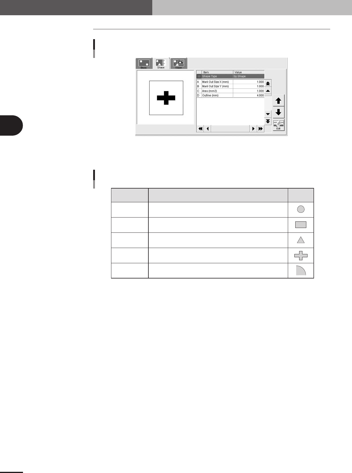
Shape Type
The Shape Type can be selected from the following 5 types.
Setting Description Example
Circle
Square
Triangle
Sp. Shape
Corner
Select to detect a circular mark.
Select to detect a square mark.
Select to detect an equilateral triangular mark.
Select to detect a special mark other than above.
Select to detect a corner of a pattern as a mark.
Shape Type settings
25412-5E-20
3 -63
3
Creating the PCB data
5. Creating the mark information
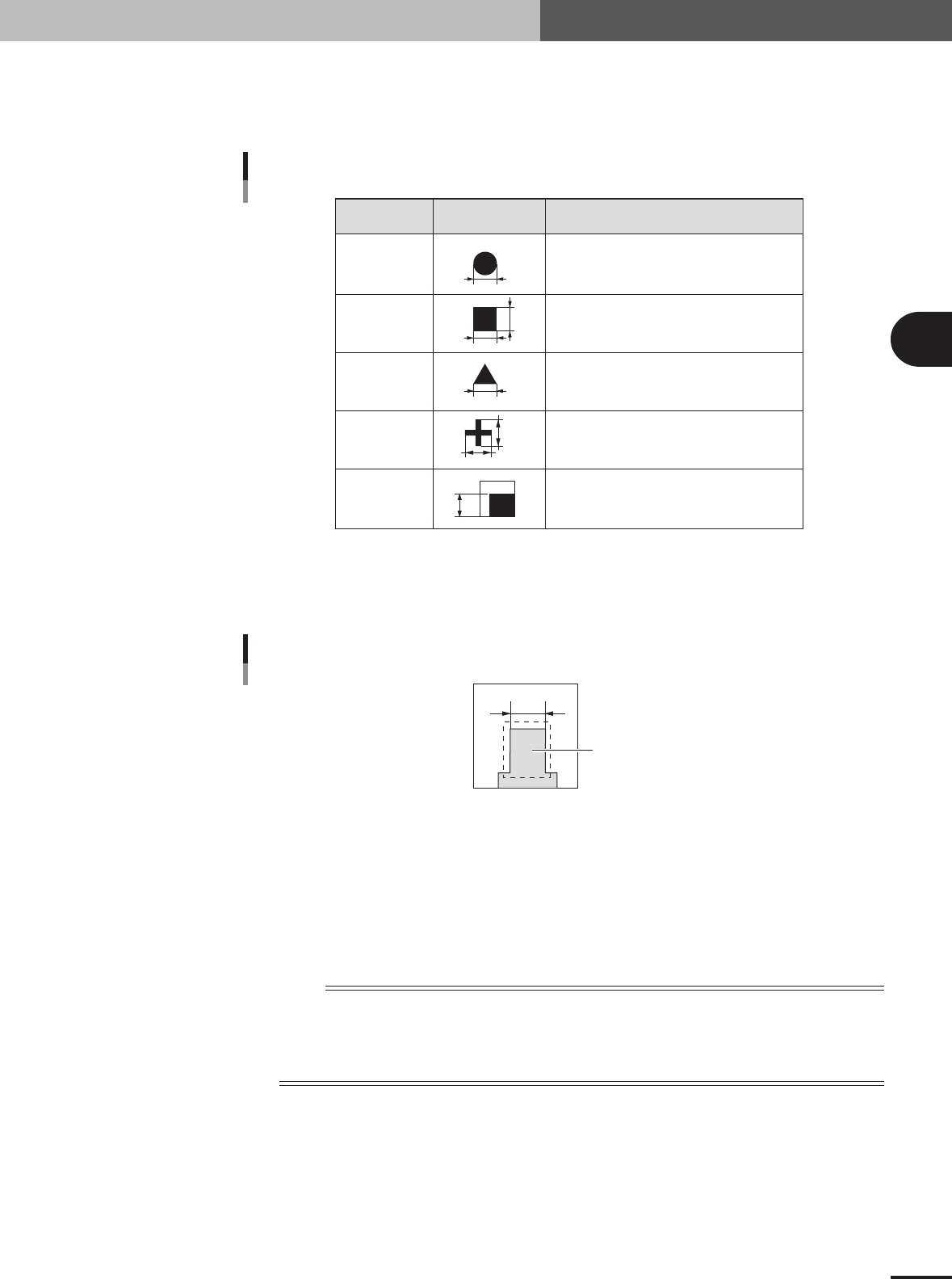
A, B: Mark Out Size X, Mark Out Size Y
Referring to the table below, enter the correct value in the mark size. This parameter is not
displayed when "Mark Type" of the Basic parameters is set to "Badmark". The Search Area
parameters appear instead.
Example Mark Out Size settingShape Type
X
X
Y
Y
Enter the diameter.
Enter the length of each side.
Enter the length of one side.
Enter the X length for the MarkOutSize X, and
the Y length for the MarkOutSize Y.
Enter the length of the shorter side displayed
within the search area.
Circle
Square
Triangle
Sp. Shape
Corner
Mark Out Size settings
25413-5E-20
Mark Out Size setting for special mark
If using a special mark with two or more edges as shown below, enter the size of the shortest side of
the rectangular area to be detected.
Rectangular area to be detected
Mark Out Size setting for special mark
23439-5E-20
C: Area
Enter the area of the mark in units of square millimeters. This parameter is displayed only when
"Shape Type" of the Shape parameters is set to "Sp. Shape".
D: Outline
Enter the perimeter length of the mark in units of millimeters.
This parameter is displayed only when "Shape Type" of the Shape parameters is set to "Sp. Shape".
n
NOTE
A recognition error may occur due to environmental conditions such as illumination. In such cases, enter a larger
value than previously used for"Tolerance" of the Vision parameters, or set the tolerance to 100%, then perform
the vision test in the Mark Adjust mode and enter the obtained data on the area and perimeter. (The mark area and
perimeter values are displayed after the vision test is complete.) Return the tolerance to the original value after the
data is obtained.