M3plus_OperationManual_e.pdf - 第133页
3 - 68 3 Creating the PCB data 5. Creating the mark information 6 Check that the mark can be recognized even if it has moved. Check that the mark can be recognized in any location within the search area. 1. Press the [Mo…
3 -67
3
Creating the PCB data
5. Creating the mark information
5
Press the [Test] button to perform the vision test.
Repeat this test several times. If no error is detected, each parameter is appropriate so
advance to the next step. If an error occurs, make adjustments with the procedure
below.
1.Press the [Cancel] button to exit the Mark Adjust mode and check whether the
parameter settings (Mark Type, Shape Type, Algorithm Type, etc.) are correct.
2.After checking the parameters, enter the Mark Adjust mode and press the [Test]
button again to run the same test. When no errors occur, move to the next step.
3.If an error still occurs, press the [Find Best] button to find an optimum threshold
level.
4.After the optimum threshold level has been found, run the vision test again.
If no errors occur, go to the next step.
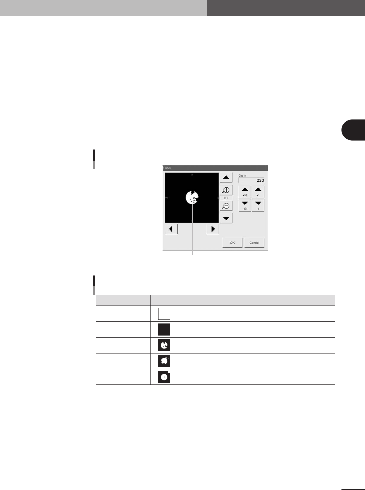
5.If the optimum threshold level could not be obtained, press the [Check] button.
A binary image appears on the vision monitor according to the current parameter
settings as shown below. Adjust the threshold level as suggested below, so that the
mark image is clearly displayed.
Binary mark image
Mark binary image
27450-5E-20
Binary image check
State Image Countermeasure Remarks
All white
All black
Noise within mark
Noise outside of mark
Other than mark in
search area
Increase the threshold level with
the arrow buttons.
Decrease the threshold with the
arrow buttons.
Increase the Cut Inner Noise level.
Increase the Cut Outer Noise level.
Reduce the Search Area size.
Adjust it till the mark is displayed.
Adjust it till the mark is displayed.
Recognition time becomes longer
as the Cut Inner Noise level is increased.
Recognition time becomes longer
as the Cut Outer Noise level is increased.
Refer to "Search Area"
explained previously.
25416-5E-20
6.Press the [Find Best] button again to find an optimum threshold level.
If the result is successful, next run the vision test. When no error occurs, advance to
the next step. If the vision test result is a fail, enter a larger value for the Tolerance
parameter on the Mark Adjust screen, then press the [Find Best] button again.
3 -68
3
Creating the PCB data
5. Creating the mark information
6
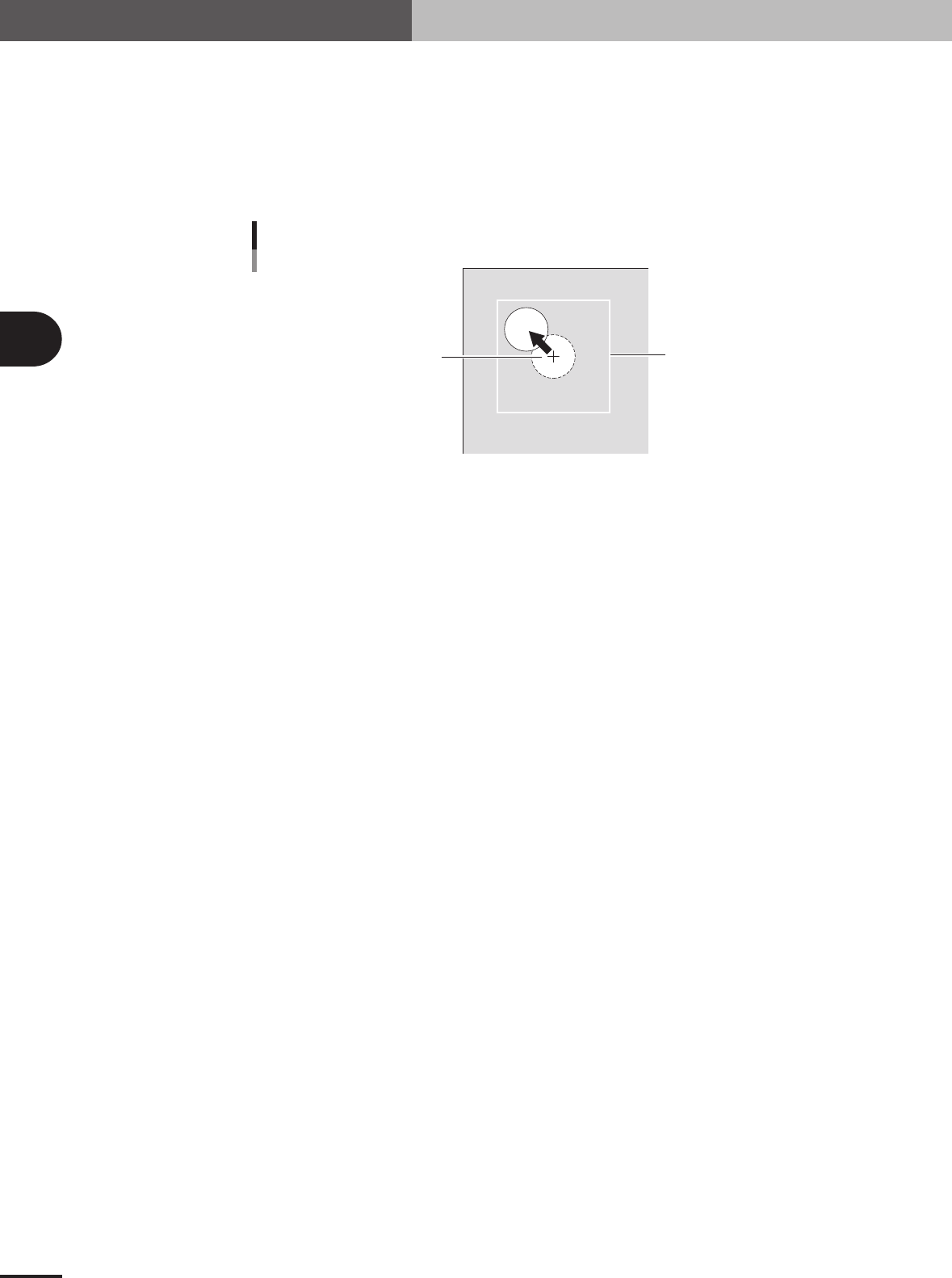
Check that the mark can be recognized even if it has moved.
Check that the mark can be recognized in any location within the search area.
1.Press the [Move Head] button to open the Move Head window.
2.Use the arrow buttons to move the mark slightly from the center of the search area.
3.Return the Mark Adjust screen and run the vision test once more.
If no error occurs, the parameter settings are satisfactory. Repeat this operation
several times, and check that no error occurs.
Search Area
Center of search area
Final check for mark recognition
23441-5E-20
7
Quit the Mark Adjust mode.
Press the [OK] button to quit the Mark Adjust mode.

Table of Contents
1. Board parameters . . . . . . . . . . . . . . . . . . . . . . . . . . . . . . . 4-1
1.1 Using the badmark functions . . . . . . . . . . . . . . . . . . . . . . . . . . . . 4-1
1.1.1 Badmark parameters . . . . . . . . . . . . . . . . . . . . . . . . . . . . . . . . . . . 4-3
2. Parts parameters . . . . . . . . . . . . . . . . . . . . . . . . . . . . . . . 4-4
2.1 Alternative components . . . . . . . . . . . . . . . . . . . . . . . . . . . . . . . . 4-4
2.1.1 Component switching flow . . . . . . . . . . . . . . . . . . . . . . . . . . . . . . 4-4
2.1.2 Setting the alternative components . . . . . . . . . . . . . . . . . . . . . . . . 4-5
2.2 Using "Parts Group No." . . . . . . . . . . . . . . . . . . . . . . . . . . . . . . . 4-7
3. Mark parameters . . . . . . . . . . . . . . . . . . . . . . . . . . . . . . . . 4-8
3.1 Pattern matching . . . . . . . . . . . . . . . . . . . . . . . . . . . . . . . . . . . . . 4-8
3.1.1 Pattern registration . . . . . . . . . . . . . . . . . . . . . . . . . . . . . . . . . . . . . 4-9
3.1.2 Using the data for pattern matching . . . . . . . . . . . . . . . . . . . . . . 4-13
4. Setup parameters . . . . . . . . . . . . . . . . . . . . . . . . . . . . . . 4-14
4.1 Halfway Continue function . . . . . . . . . . . . . . . . . . . . . . . . . . . . 4-14
4.1.1 Loading the saved data . . . . . . . . . . . . . . . . . . . . . . . . . . . . . . . . 4-15
4.1.2 Editing mount flags . . . . . . . . . . . . . . . . . . . . . . . . . . . . . . . . . . . 4-15
5. Edit Assistant function . . . . . . . . . . . . . . . . . . . . . . . . . . 4-16
5.1 Switching to the Edit Assistant screen . . . . . . . . . . . . . . . . . . . . 4-16
5.2 Selecting a range of rows . . . . . . . . . . . . . . . . . . . . . . . . . . . . . . 4-17
5.3 Editing rows . . . . . . . . . . . . . . . . . . . . . . . . . . . . . . . . . . . . . . . . 4-18
5.4 Find and replace . . . . . . . . . . . . . . . . . . . . . . . . . . . . . . . . . . . . 4-19
5.5 Renumber . . . . . . . . . . . . . . . . . . . . . . . . . . . . . . . . . . . . . . . . . 4-20
6. Recognition image check and save function . . . . . . . . 4-21
7. Fixed board matching . . . . . . . . . . . . . . . . . . . . . . . . . . 4-23
7.1 How to set up the fixed board matching function . . . . . . . . . . . 4-25
Chapter 4 Using the advanced functions