M3plus_OperationManual_e.pdf - 第138页
4 - 3 4 Using the adv anced functions 1.1.1 Badmark parameters Selecting the [Badmark] tab opens the screen for setting badmark mark parameters and their coordinates. Set these parameters as explained below when using th…
4 -2
4
Using the advanced functions
1. Board parameters
Badmark operation
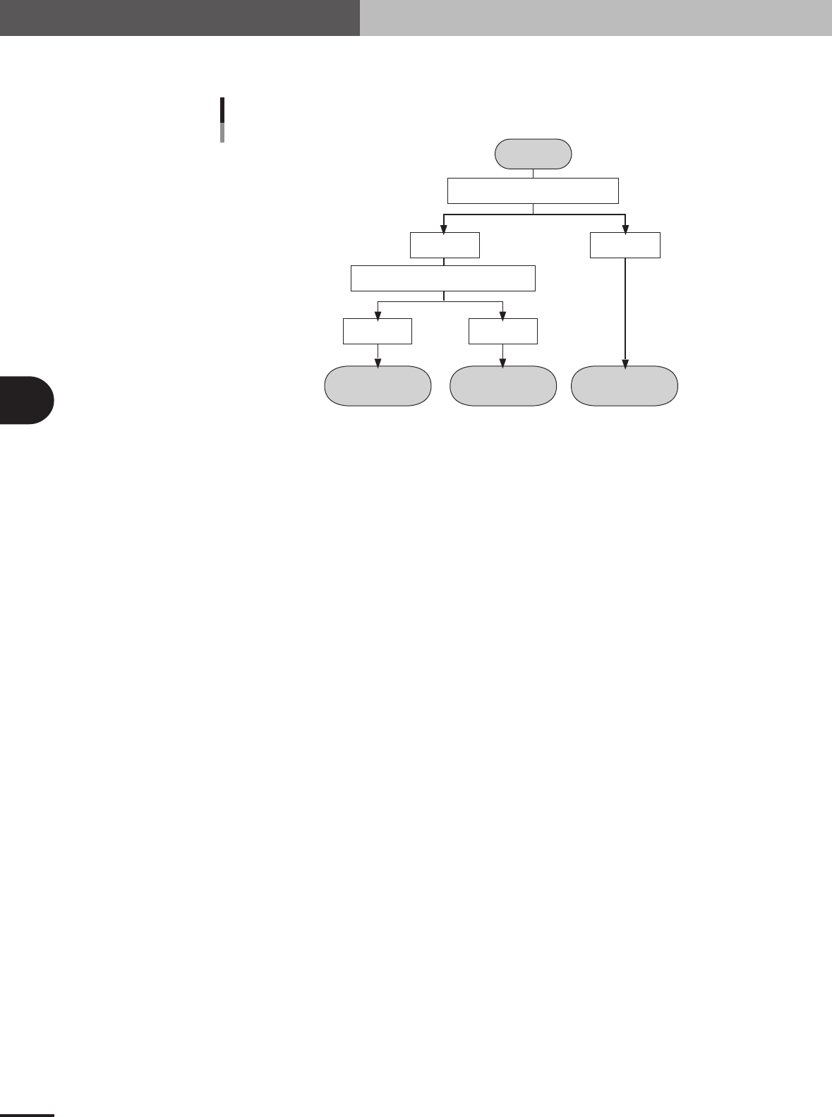
The flow chart below shows typical methods for setting a board badmark and block badmark.
Operation
not performed for
the block
Operation
performed for
the block
Operation
performed for
all blocks
Start
Search PCB badmark
Detected Not detected
Search block badmark
Badmark operation flows
Detected Not detected
23415-5E-20
4 -3
4
Using the advanced functions
1.1.1 Badmark parameters
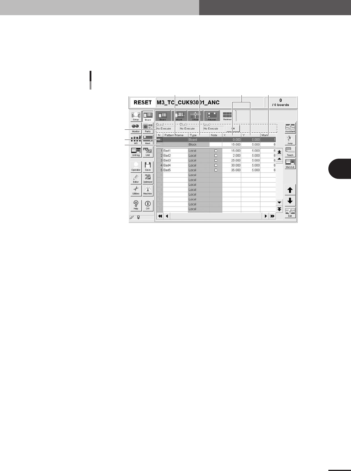
Selecting the [Badmark] tab opens the screen for setting badmark mark parameters and
their coordinates. Set these parameters as explained below when using the badmark
function. Two or four badmarks are used as a set, but it is okay if each mark is different
in shape. Badmark mark data must be registered in the mark information beforehand.
(See "5. Creating the mark information" in chapter 3.)
4
1
567
2
3
Badmark parameter screen
27410-5E-20
1 Board, Block, Local
Badmark functions are broadly classified into three types: "Board" badmark function specified for a
PCB, "Block" badmark function specified for each block of a multi-block PCB, and "Local" badmark
function related to mounting data. The badmark function you want to use should be set to "Execute".
To change the setting, press the [Edit] button on the right end.
2 Board
On the top line of the parameter list, set the board badmark data.
3 Block
On the second line of the parameter list, set the block badmark data.
4 Pattern Name
Enter the badmark name here. (No names can be entered on the top and second lines.)
5 Type
Badmark function types are specified here. (These cannot be changed.)
6 X, Y
Enter the XY coordinates of the badmark relative to the PCB origin in millimeters. You can perform
teaching with the [Teach] button.
7 Mark
Enter the mark No. for the badmark (mark No. registered as mark in the mark information).
1. Board parameters
4
Using the advanced functions
4-4
2. Parts parameters
2.1 Alternative components
When components in a feeder is used up during operation, the alternative component
function allows the machine to pick up components from another feeder specified as
alternative components.
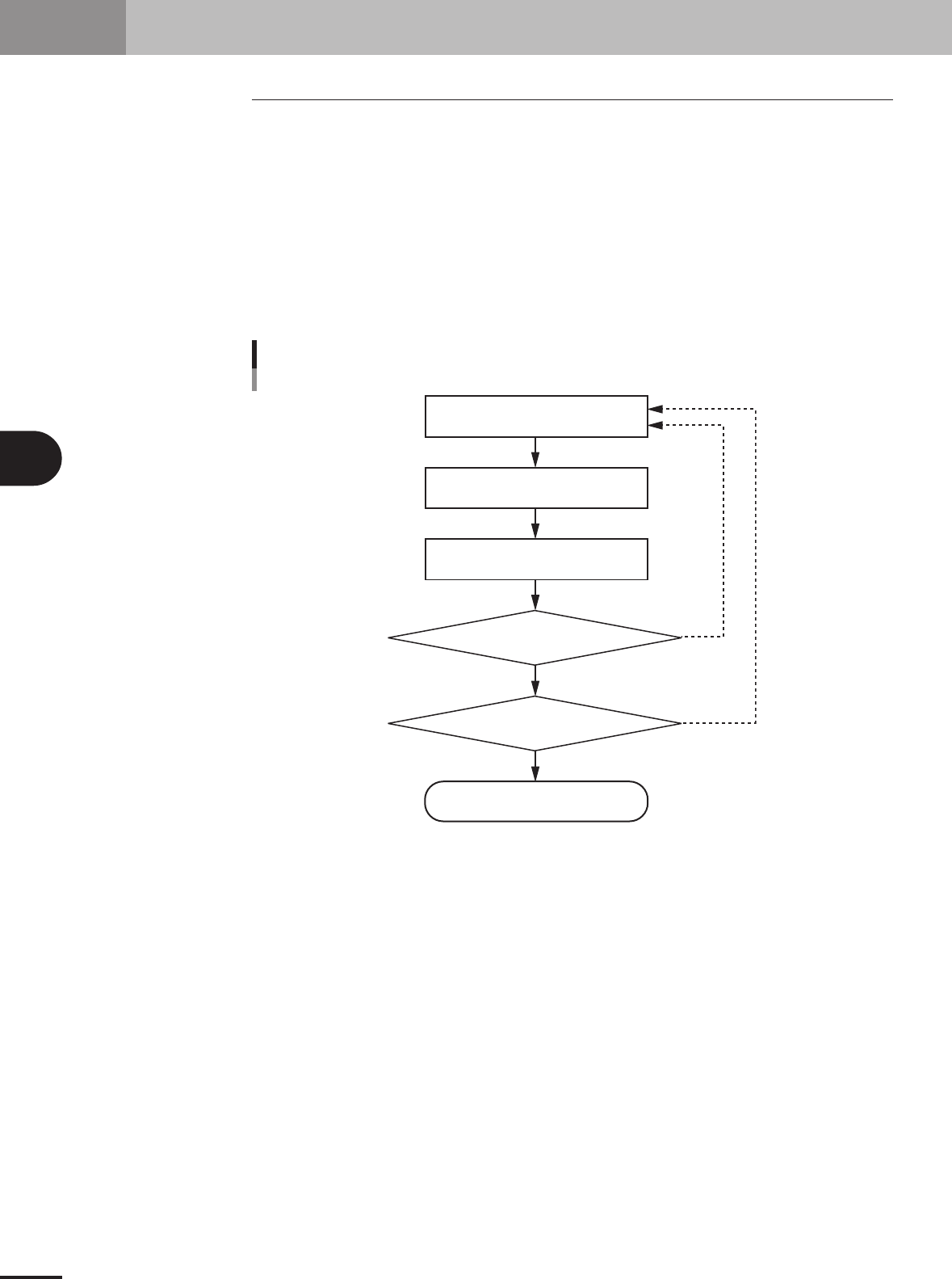
2.1.1 Component switching flow
In the Alternative component function, component feed is switched in the operation flow
explained below.
When the components in the current feeder run out, the machine allows automatic switch-
ing to the alternative component feeder without interrupting operation. When one cycle
using alternative components is complete, the machine stops and a message asking you to
resupply the components then appears.
YES
YES
NO
NO
Component switch flow
Tape feeder/stick feedercomponents
Out of components
Running
Machine stops
Automatically switches
to alternative components
Is one cycle
using alternative component group
complete?
Were components
resupplied during running?
23448-5E-20