M3plus_OperationManual_e.pdf - 第144页
4 - 9 4 Using the adv anced functions 3. Mark parameters 3.1.1 Pattern registration To utilize pattern matching, you must register the reference pattern in the template. 1 Decide on the pattern. Decide which pattern you …
4
Using the advanced functions
4-8
3. Mark parameters
3.1 Pattern matching
Pattern matching is a function for correcting PCB dimensional or reference hole errors,
positioning errors occurring from the PCB clamping mechanism, or local distortion of the
PCB. To use this function, the image of a particular PCB pattern must be registered as
the template. Errors or distortion are corrected by comparing the template you registered
with an actual pattern being recognized. Pattern matching is useful when the fiducial
function cannot be used, for example, if the PCB has no fiducial marks or the mark does
not match any recommended marks.
n
NOTE
Any pattern can be used, but the pattern image should be smaller than about 1/4th of the monitor and must meet
the following conditions.
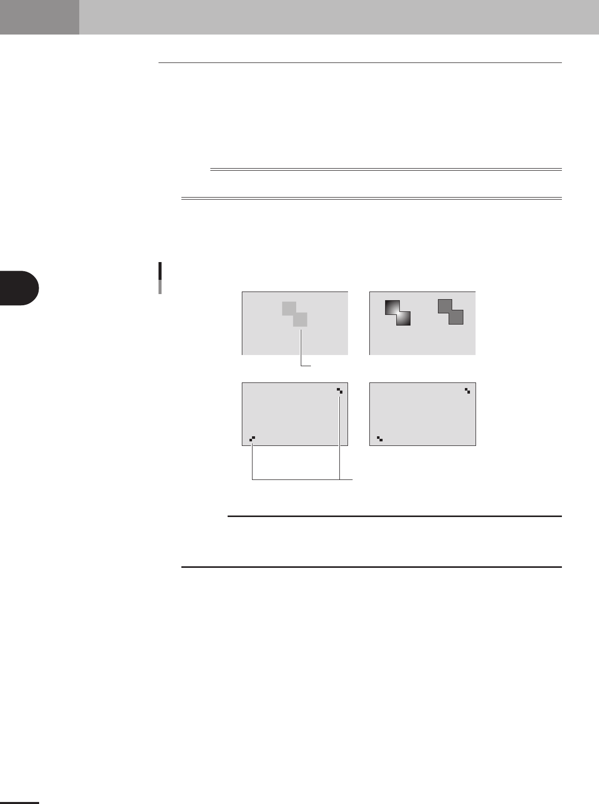
Pattern conditions
• Each pattern clearly contrasts with the PCB. (It is okay if the outline of each pattern is definite.)
•A pair of patterns are diagonally opposing on the PCB.
NG
NG
OK
PCB
PCB
OK OK
Low contrast
Not the same direction
Pattern conditions
23442-5E-20
c
CAUTION
Pattern matching requires a longer recognition time than normal mark recognition and its
accuracy may drops slightly when compared to cases using round or square marks. It is not
necessary to use pattern matching for marks which can be correctly recognized with "Algorithm
Type" set to "Normal".
4 -9
4
Using the advanced functions
3. Mark parameters
3.1.1 Pattern registration
To utilize pattern matching, you must register the reference pattern in the template.
1
Decide on the pattern.
Decide which pattern you want to use for pattern matching. Select a pair of patterns
that meet the conditions explained previously.
2
Enter the pattern name in the mark information.
Open the Mark screen and, in the Mark Name column, enter the name that you can
easily identify as a pattern.
3
Set the parameters.
Set the parameters as follows.
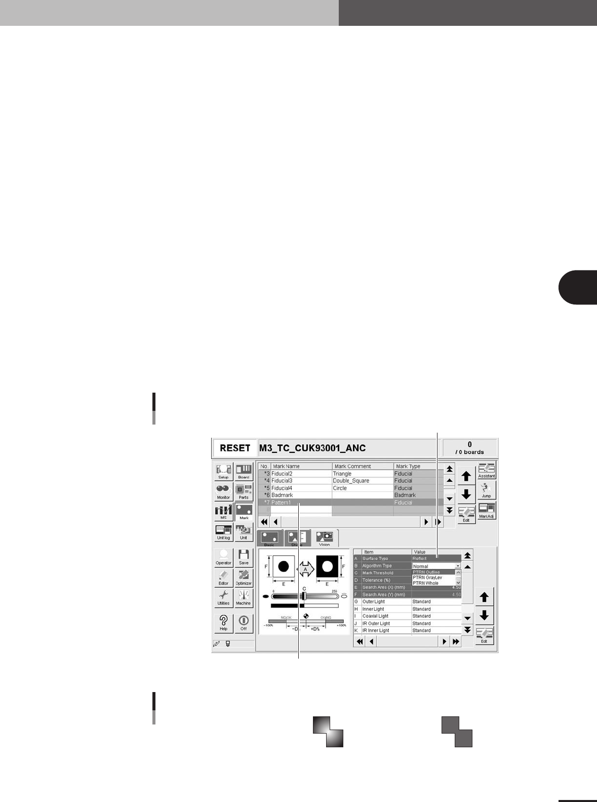
1.Set "Mark Type" of the Basic parameters to "Fiducial".
2.Set "Algorithm Type" of the Vision parameters to "PTRN Outline" or "PTRN
GrayLev".
• PTRN Outline:
In most cases, select this parameter for pattern matching. When the outline is
definite, the pattern can be recognized even if uneven brightness portions are
present inside the pattern.
• PTRN GrayLev:
Selecting this parameter is more effective in recognizing a pattern whose brightness
is uniform inside the pattern. Since the entire pattern is recognized, this parameter
setting requires a longer time than in the "PTRN Outline" setting and also the data
size will be larger.
• PTRN Whole:
Selecting this parameter is effective in acquiring details of a pattern image. Since
the entire pattern is recognized and less compressed, this parameter setting requires
a longer time than in the "PTRN GrayLev" setting and also the data size will be
even more larger.
Enter the pattern name.
Pattern setting
Set to "PTRN Outline", "PTRN GrayLev" or "PTRN Whole".
27451-5E-20
Pattern recognition types
PTRN outline
Brightness is uneven inside the pattern
but the outline is clearly defined.
PTRN GrayLev
PTRN Whole
Brightness is uniform inside the pattern.
23443-5E-20
4 -10
4
Using the advanced functions
3. Mark parameters
4
Press the [Adjust] button to open the Mark Adjust screen.
Mark Adjust screen
27453-5E-20
5
Set the PCB on the conveyor and clamp it.
6
Move the head so the pattern is displayed in the center of the vision
monitor.
Use the Move Head button to move the head. When the head is positioned, press the
[OK] button to return to the Mark Adjust screen.
7
Adjust the mark lighting levels.
Press the [Light] button and adjust the mark lighting levels so that the pattern can be
clearly seen.
8
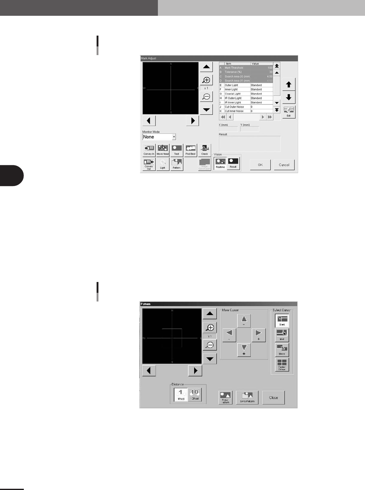
Press the [Pattern] button.
The Pattern registration screen appears as shown below.
Pattern registration screen
27454-5E-20