M3plus_OperationManual_e.pdf - 第179页
5 Editing the PCB data 5- 14 2. Block of fset A multi-block PCB is a printed circuit board consisting of two or more independent printed circuits of the same type. Each printed circuit on a multi-block PCB is called a &q…
5 -13
5
Editing the PCB data
1. Using the Editor
1.5 Multiplying the Component Data
This function allows component data to multiply into two or more units of the same data.
This means that the multiplied data can be supplied from multiple feeders. When a large
amount of the same components are used for one PCB, this function shortens the time
required to produce a PCB
1
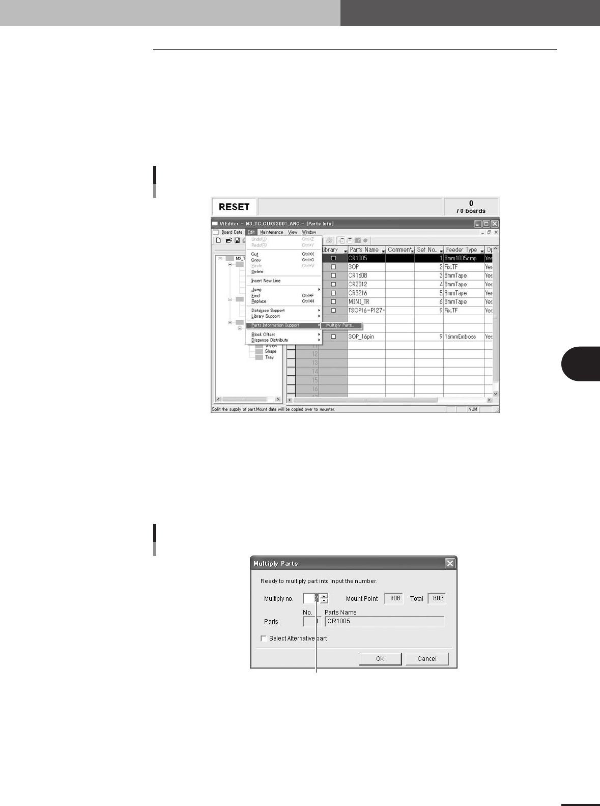
Display the "Parts Info" data table.
Click the "Parts Info" icon in the work space.
2
Select the data line of the component to be multiplied.
"Multiply Parts" command
27520-5E-20
3
Multiply the selected component.
1.Select "Component Information Support" - "Multiply Parts" from the Edit menu.
The "Multiply Parts" dialog box appears.
2.In the "Multiply No." box, set the desired number you want to obtain.
3.Check the "Select Alternative Part" checkbox if the component is used as an
alternative component.
Enter or select the number to multiply data.
"Multiply Parts" dialog box
27521-5E-20
4.Click the [OK] button.
Component multiplication is performed.
5.When the dialog box appears indicating the component multiplication has been
completed, click the [OK] button. The dialog box closes.
5
Editing the PCB data
5-14
2. Block offset
A multi-block PCB is a printed circuit board consisting of two or more independent printed circuits of
the same type. Each printed circuit on a multi-block PCB is called a "block". Setting the block offset
allows the machine to repeat the same mounting operation in each block on a PCB, based on the
reference block data. This function therefore greatly saves the time required for creating data on multi-
block PCBs.
Block Multi-block PCB
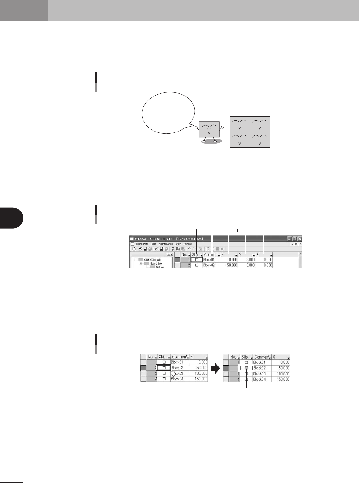
The offset
function allows you
to change the entire
PCB data just by
editing the data for the
reference block.
Block repeat function
63436-5E-20
2.1 Creating the block offset data
1
Display the block offset information.
On the tree in the work space, click the Block Offset Info icon. The detail view
window switches to the block offset information.
Block offset information display
12 3 4
27522-5E-20
2
Set the reference block offset data.
The block closest to the machine origin is normally viewed as the reference block.
Enter this reference block offset data in the No. 1 line by referring to the following
descriptions.
1 Skip
Place a checkmark when not mounting components in this block.
Selecting the Skip checkbox
A checkmark appears.
27523-5E-20
5 -15
5
Editing the PCB data
2. Block offset
2 Comment
Type any desired comment on the block offset in alphanumeric characters.
c
CAUTION
Spaces cannot be used. Use underbars ( _ ) for spaces.
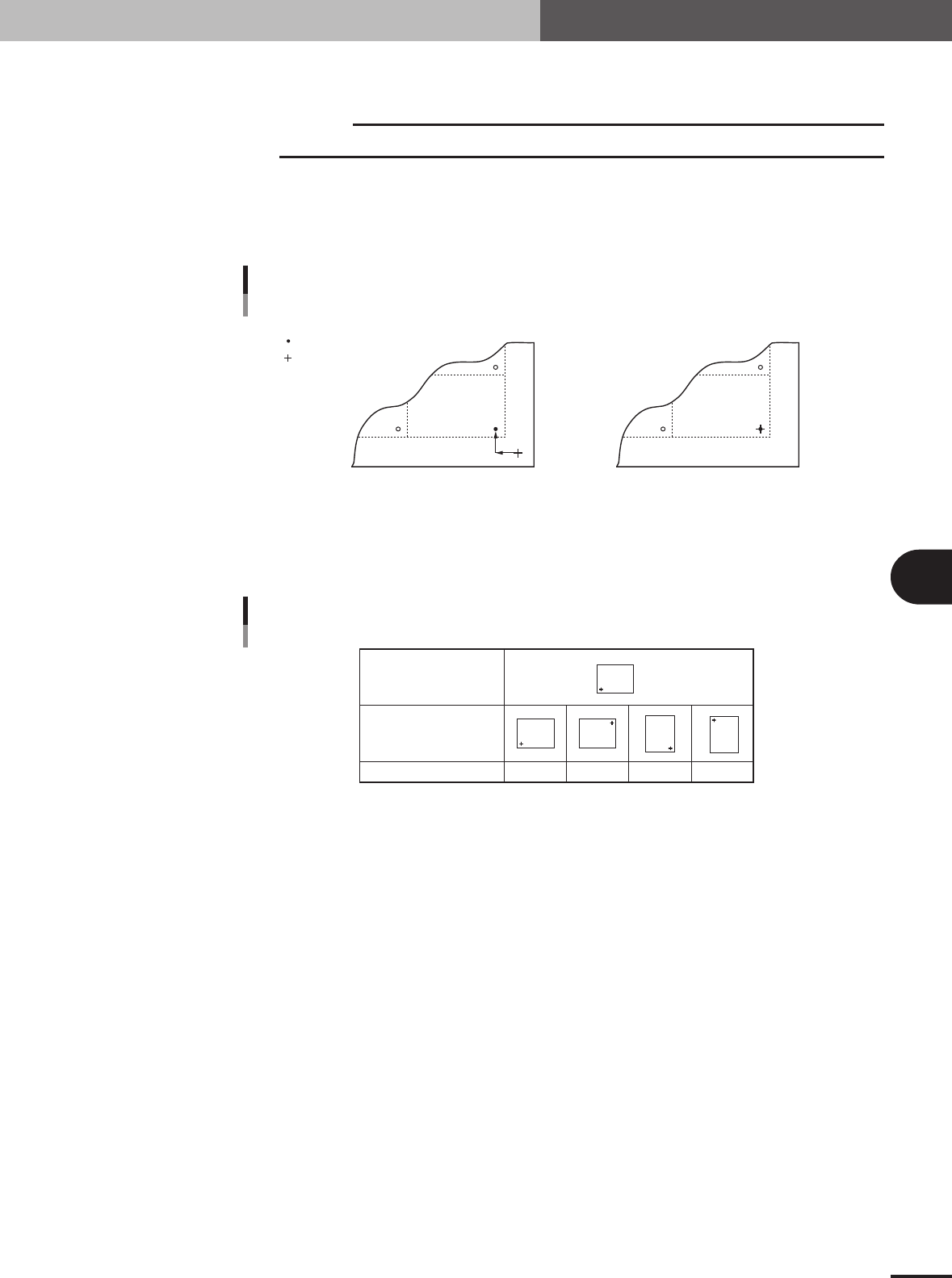
3 X, Y
Enter the XY coordinates of the origin of this block relative to the PCB origin. Usually, the PCB
origin is specified at the same position as the reference block origin, so enter "0.00, 0.00" as the XY
coordinates.
PCB origin is at the same position
as reference block origin
PCB origin is at a position other than
reference block origin
PCB origin
Reference block origin
XY data
PCB origin and reference block origin
X
Y
63437-5E-20
4 R
Enter "0.00" for the reference block.
Reference block direction
Block direction
R data 0° 180° 90° -90°
Block
Block
Block
Block
Block
R data
65418-5E-20