M3plus_OperationManual_e.pdf - 第188页
5 - 23 5 Editing the PCB data 3. Optimizing the data 8 Designate the "Feeder Set Condition" conditions. Feeder Set Condition 27463-5E-20 NO The data is not optimized. ALL FEEDERS FIXED Only the component mounti…
5 -22
5
Editing the PCB data
3. Optimizing the data
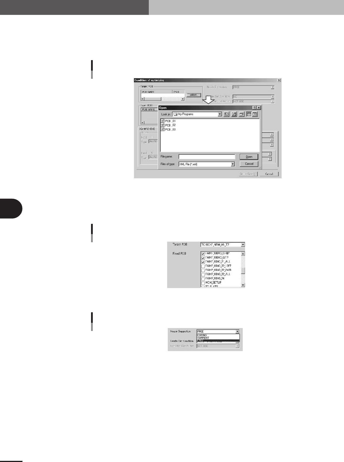
When "XML" was selected in step 3:
1. Press the [New Pcb] button.
The optimizer condition setting screen for "XML" will open.
2. Press the [Select] button to select the PCB to be optimized.
Selecting XML PCB data
27460-5E-20
6
Select the fixed PCB.
The fixed PCB refers to PCB data using the feeder set positions which are not to be
changed with data optimization. Data optimization will be carried out without
changing the setup of the PCB data checked here.
Selecting the fixed PCB (VIOS)
27461-5E-20
7
Select "Nozzle Suggestion".
Nozzle Suggestion
27462-5E-20
FREE
The nozzle is automatically set so that the cycle time is the shortest.
EDITING
When this is selected, data can be input in the bottom left "Nozzle" boxes, and the
nozzle used for each head can be manually set.
CURRENT
The settings applied before data optimization are used.

5 -23
5
Editing the PCB data
3. Optimizing the data
8
Designate the "Feeder Set Condition" conditions.
Feeder Set Condition
27463-5E-20
NO
The data is not optimized.
ALL FEEDERS FIXED
Only the component mounting order and mounting head are optimized. The feeder
set positions are not optimized.
NO SET POS. FEEDER MOVE
The component mounting order and mounting head are optimized, and the opti-
mum feeder set No. is assigned to data for which the "Feeder Set No." in the
component information is set to "0".
MOVE WITHIN TABLE
The component mounting order and mounting head are optimized, and the feeder
set position in each feeder plate is optimized.
ALL FEEDERS MOVE
The component mounting order and mounting head are optimized, and all feeder
set positions other than the fixed components are optimized.
MOVE + FIXED DATA MATCH
The fixed component matching is performed. After that, the mounting order,
mounting head and feeder set positions other than the fixed components are
optimized.
9
Designate the priority feeder plate.
When the front/back or left/right priority feeder plate is designated, more feeders will
be arranged on that feeder plate when the feeder position is optimized.
0
Save the settings.
Press the [Setting Save] button.
q
Repeat the above steps to optimize other PCB data.
5 -24
5
Editing the PCB data
3. Optimizing the data
3.2 Executing
Optimize the PCB data after setting the optimization conditions.
1
Load the PCB data to be optimized.
The "List of boards for which optimization conditions are set" will appear at the left
of the screen. Set the cursor to the PCB to be optimized, and press the [Right arrow]
button. The PCB data will be loaded in, and the PCB name will appear in the "List of
optimization boards" on the right side. When the [Cycle Time Estimation] button is
pressed, the estimated time cycle after optimization can be confirmed.
Press this button to load the PCB data from the left list into the right list.
Selecting the PCB data to be optimized
27457-5E-20
2
Press the [Execute] button and start optimization.
All of the selected board data will be optimized, and the results will be displayed.
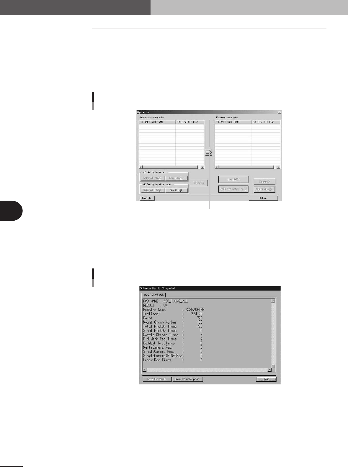
3
Check the results.
Press the [Result View] button, and check the results.
Optimization result display
27465-5E-20
4
Save the data.
Press the [Save the result] button, and save the data. If the data is not to be saved,
press the [Close] button and quit optimization.