M3plus_OperationManual_e.pdf - 第213页
在线预览 M3plus_OperationManual_e.pdf PDF 文档。

Table of Contents
1. Specifications . . . . . . . . . . . . . . . . . . . . . . . . . . . . . . . . . A-1
1.1 Air regulator unit . . . . . . . . . . . . . . . . . . . . . . . . . . . . . . . . . . . . . A-1
1.2 Connection between machines . . . . . . . . . . . . . . . . . . . . . . . . . . A-2
1.2.1 PREVIOUS INTERFACE connector . . . . . . . . . . . . . . . . . . . . . . . . A-3
1.2.2 NEXT INTERFACE connector . . . . . . . . . . . . . . . . . . . . . . . . . . . . A-3
1.3 Power connection terminals . . . . . . . . . . . . . . . . . . . . . . . . . . . . A-4
2. Alignment Type glossary . . . . . . . . . . . . . . . . . . . . . . . . B-5
2.1 Alignment Type . . . . . . . . . . . . . . . . . . . . . . . . . . . . . . . . . . . . . . . B-5
2.1.1 Alignment Type definition . . . . . . . . . . . . . . . . . . . . . . . . . . . . . . .B-7
2.1.2 Detecting the component center and tilt . . . . . . . . . . . . . . . . . . . . B-9
2.2 Using special recognition settings . . . . . . . . . . . . . . . . . . . . . . . B-10
2.2.1 QFP recognition mode . . . . . . . . . . . . . . . . . . . . . . . . . . . . . . . .B-10
2.2.2 Single connector recognition mode . . . . . . . . . . . . . . . . . . . . . . .B-10
2.2.3 4-way connector recognition mode (Con-NSEW) . . . . . . . . . . . .B-10
2.2.4 Mark recognition mode . . . . . . . . . . . . . . . . . . . . . . . . . . . . . . . .B-11
2.2.5 Special rectangle (Sp. Quad) recognition mode . . . . . . . . . . . . .B-18
2.2.6 PLCC (SOJ) base recognition mode . . . . . . . . . . . . . . . . . . . . . . . B-19
2.2.7 Center-of-gravity detection (probe recognition mode) . . . . . . . . .B-21
Appendix
A
Specifications
A -1
1. Specifications
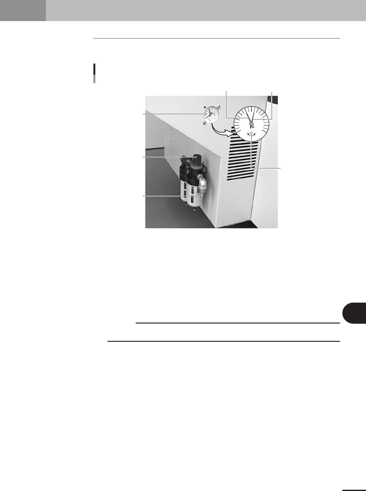
1.1 Air regulator unit
The air pressure regulator is located on the lower left side of the machine. The air pres-
sure regulator must be correctly set to supply the machine at an optimum air pressure.
Air supply
Source air connector
Pressure regulator
0.4
0.5
0
0.1
MPa
0.2
0.3
0.6
0.7
0.8
0.9
1
Pressure drop
detection level (red)
Pressure indicator
needle (black)
Pressure meter
Adjust screw
(for pressure drop
detection level setting)
23120-5E-20
Pressure meter
Shows the supply air pressure (black needle) and pressure-drop detection level (red needle). Use the
pressure regulator knob to set the supply air pressure and the adjustment screw on the meter to set the
pressure-drop detection level, so that each needle points to the following value.
Supply air pressure (black needle) : 0.55MPa
Pressure-drop detection level (red needle) : 0.4MPa
Pressure regulator
Use to adjust the supply air pressure so that the black needle on the meter reads the specified value
(0.55MPa).
c
CAUTION
Before setting the air pressure, make sure that the pressure from the primary air supply is
between 0.6 and 0.7MPa.
Source air connector
Prepare an air hose with an inner diameter of at least 8mm having a 30SH socket (Nitto Koki, or
equivalent), and connect it to this connector. Use dry, clean air passed through an air filter.