M3plus_OperationManual_e.pdf - 第214页
A Specifications A - 1 1. Specifications 1.1 Air regulator unit The air pressure regulator is located on the lower left side of the machine. The air pres- sure regulator must be correctly set to supply the machine at an …
A
Specifications
A -1
1. Specifications
1.1 Air regulator unit
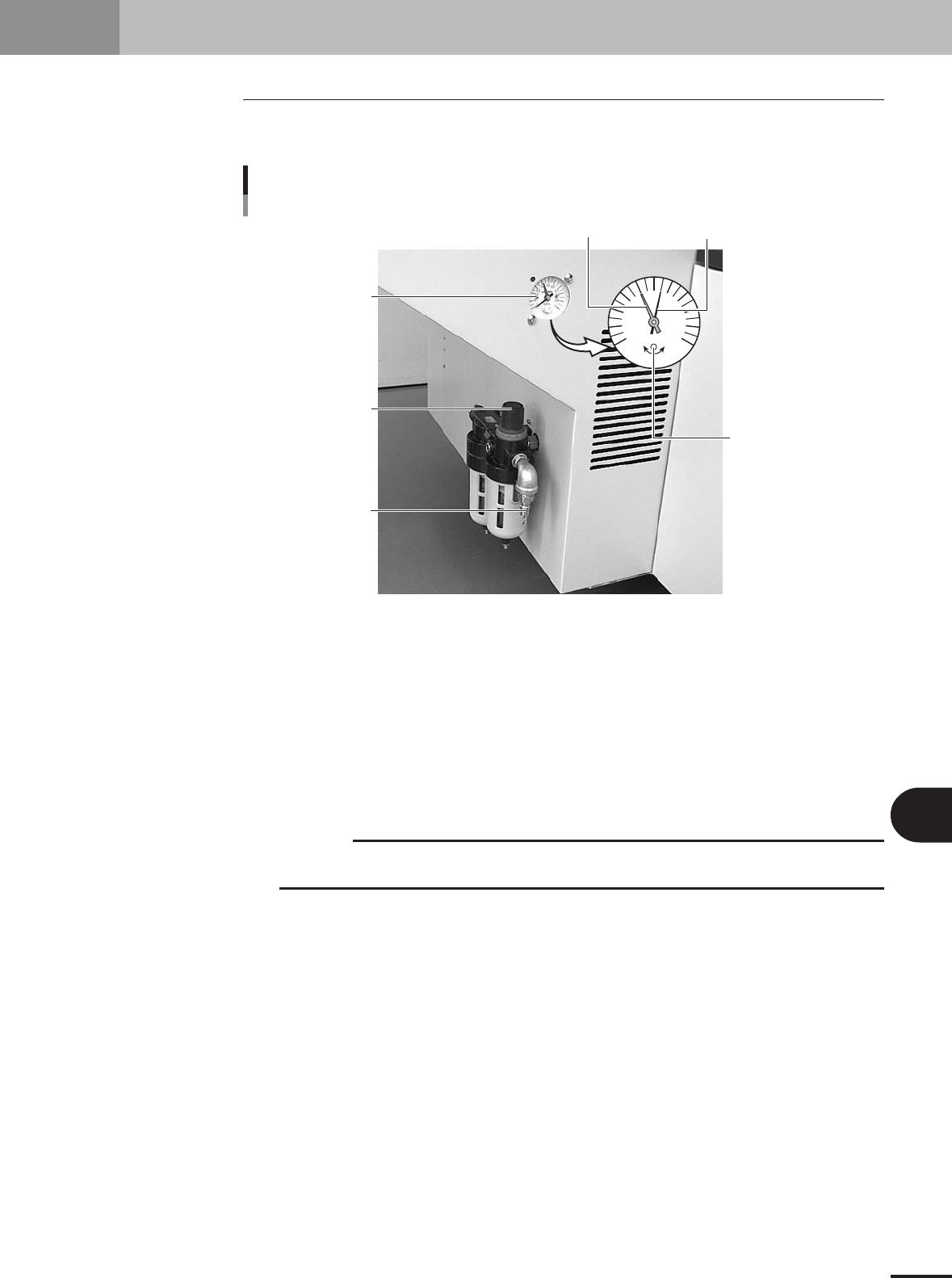
The air pressure regulator is located on the lower left side of the machine. The air pres-
sure regulator must be correctly set to supply the machine at an optimum air pressure.
Air supply
Source air connector
Pressure regulator
0.4
0.5
0
0.1
MPa
0.2
0.3
0.6
0.7
0.8
0.9
1
Pressure drop
detection level (red)
Pressure indicator
needle (black)
Pressure meter
Adjust screw
(for pressure drop
detection level setting)
23120-5E-20
Pressure meter
Shows the supply air pressure (black needle) and pressure-drop detection level (red needle). Use the
pressure regulator knob to set the supply air pressure and the adjustment screw on the meter to set the
pressure-drop detection level, so that each needle points to the following value.
Supply air pressure (black needle) : 0.55MPa
Pressure-drop detection level (red needle) : 0.4MPa
Pressure regulator
Use to adjust the supply air pressure so that the black needle on the meter reads the specified value
(0.55MPa).
c
CAUTION
Before setting the air pressure, make sure that the pressure from the primary air supply is
between 0.6 and 0.7MPa.
Source air connector
Prepare an air hose with an inner diameter of at least 8mm having a 30SH socket (Nitto Koki, or
equivalent), and connect it to this connector. Use dry, clean air passed through an air filter.
A -2
A
Specifications
1. Specifications
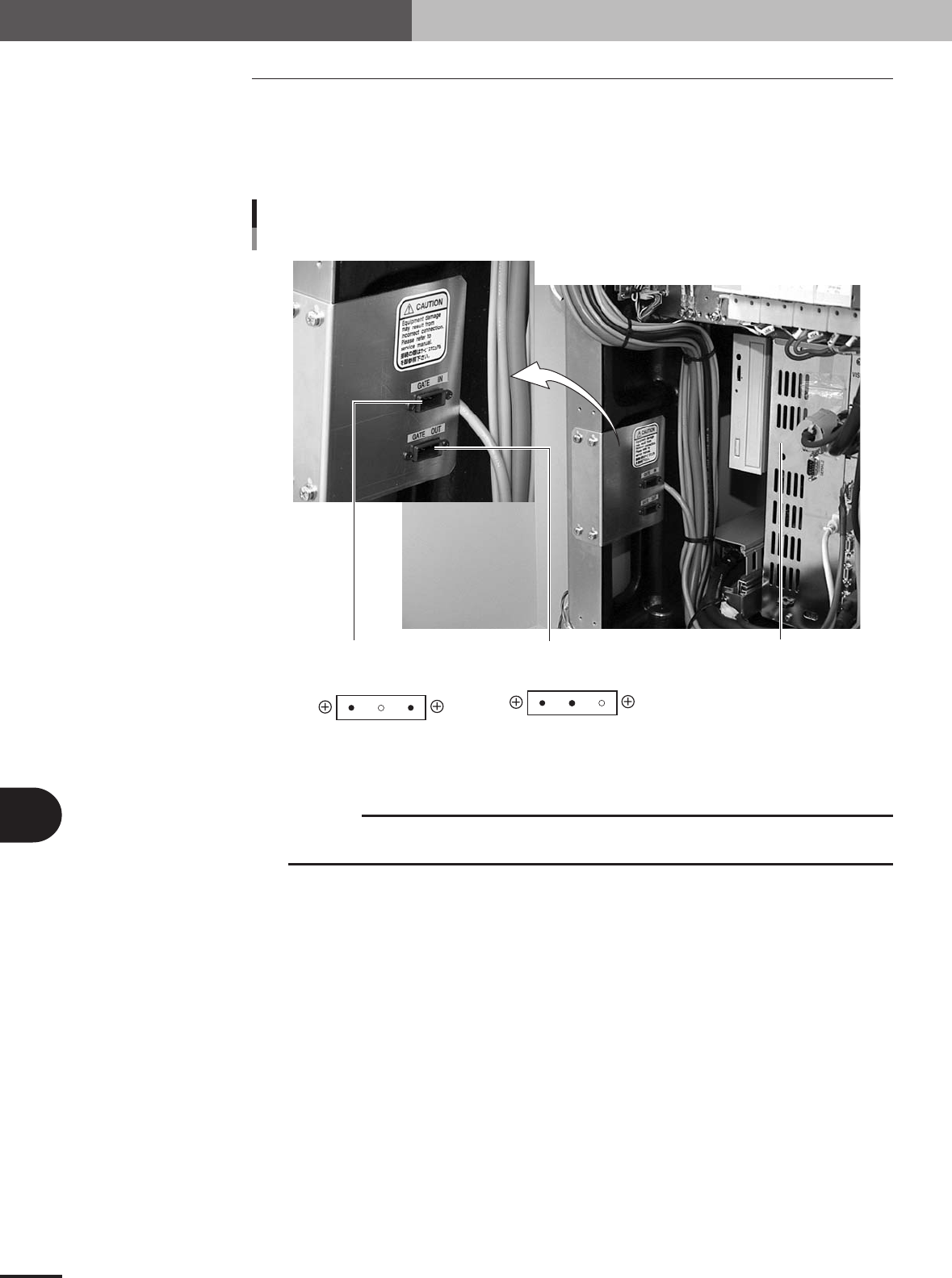
1.2 Connection between machines
The mounter ejects the finished PCB when it receives a signal from the machine in the
next process, and then sends a signal to the machine in the preceding process to request
another PCB. The "NEXT INTERFACE" connector connects to the machine in the next
process, and the "PREVIOUS INTERFACE" connector connects to the machine in the
preceding process. Both connectors are located inside the front panel of the machine.
Controller
PREVIOUS
INTERFACE
NEXT
INTERFACE
NEXT and PREVIOUS INTERFACE connectors
3
1 2
2
1 3
AMP 2-178802-3
3-pin panel type
keying Y
AMP 2-178802-3
3-pin panel type
keying X
23121-5E-20
c
CAUTION
A dedicated cable is separately required when the machine in the preceding process is not M
cube / M cube plus. (Refer to the specification sheet for details.)