M3plus_OperationManual_e.pdf - 第222页
B - 9 B Alignment T ype glossar y 2. Alignment T ype glossar y 2.1.2 Detecting the component center and tilt In vision systems, the center position and tilt of a component are detected by several methods according to the…

B -8
B
Alignment Type glossary
2. Alignment Type glossary
Alignment Group: Connector
• Con-E (Connector E)
This is for components having the same leads only in the E direction.
• Con-NSEW (Connector NSEW)
This setting is suited for components having leads in four directions of N, S, E and W, but the
number of leads and their shape in each direction are different. Only one type of lead shape can be
set for each direction.
• Odd.Con
Use this setting for connectors suitable for "Con-E" having off leads.
• Special
This can be used for components having irregularly arranged leads. For example, components having
leads in four directions of N, S, E and W like "Con-NSEW", but whose number of leads and the
shape in each direction are different. Although "Con-NSEW" allows setting only one type of lead
shape in each direction, "Special" allows setting two types, making it usable for various components
with irregular shapes. This setting cannot be used with the lead coplanarity function.
Alignment Group: Special
• Odd.Chip
This setting automatically determines whether to recognize a component as "white" or "black",
making it suited for components such as bare chips which are difficult to judge as reflective or non-
reflective against the background (PCB). This mode is also appropriate for BGA components with a
light reflective portion on the body.
• AsMark
This setting recognizes components as a mark and is therefore suited for specially shaped compo-
nents.
• Sp. Quad
This is used for square or rectangular components which reflect light at the four sides of the package
making it difficult to distinguish the leads from the package.
• Gravity
This detects the center-of-gravity of a target (black or white) in the specified area, allowing reliable
recognition of various components with irregular shapes. When using this setting, test-mount the
component after setting the data, and check the mounting shift (distance from center of mounting
position to center of the component). Then enter the shift amounts in "Cntr. Offset XYR" of the
Shape parameters.
• Ignore
This does not perform image processing.
Alignment Group: Ball
• Simple BGA
This is specially for BGA components. The number of ball leads can be checked, but the ball lead
positions and nicks are not checked.
• BGA
This is specially for BGA components. The ball lead positions can be edited to check the lead
positions and nicks.
• FlipChip
This is specially for flip chip components and can be used only when a vision camera with a side
lighting unit is used.
B -9
B
Alignment Type glossary
2. Alignment Type glossary
2.1.2 Detecting the component center and tilt
In vision systems, the center position and tilt of a component are detected by several
methods according to the type of component.
Depending on the component, the center position and tilt of a component found in recog-
nition processing might not always match the center and tilt of the actual component. In
those cases, the detected data must be corrected (offset) based on the library data.
In library data, the center of the dimensional outline is usually defined as the component
center. The positions of leads on all sides of the component are defined based on this
component center. In recognition processing, the component position (hereafter "recogni-
tion center") is usually found as the center-of-gravity position for all component lead
tips.
The center of the dimensional outline of a component such as a QFP matches the recogni-
tion center so the recognition center of these components can be used as the component
center.
The recognition center will not usually match the component center if the left/right and
top/bottom of a component are not symmetrical with each other.
In recognition processing in such cases, the center-of-gravity position (average value for
each X/Y coordinate) for all lead tips is found as the recognition center. The center-of-
gravity positions for all leads and component center offsets are then found beforehand
from the defined component data (library data). Based on this information, the center
positions found from recognition processing are correctly offset to find the component
center. The tilt is found beforehand in the same way by correcting the recognition results
using the offset amount.
So when there is a discrepancy or error between the library data and the actual compo-
nent, that error prevents correctly offsetting the component center position and leads to
problems in component mounting. In components that require offset correction (mainly
asymmetrical components) it is essential that the library data be set correctly.
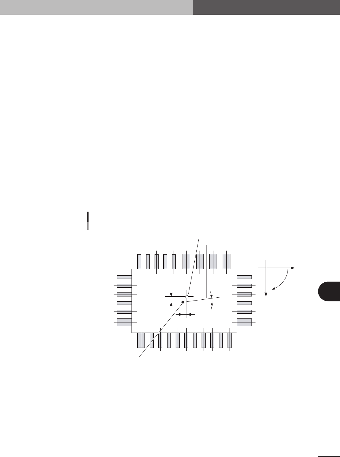
Offset X
Offset Y
Offset R
Detected angle
Coordinate system
Center of dimensional outline
Y
X
R
Center of all lead tips
Component center detection
23B01-5E-20

B -10
B
Alignment Type glossary
2. Alignment Type glossary
2.2 Using special recognition settings
If a component cannot be recognized with normal "Alignment Type" settings, use special
recognition algorithms. Methods for setting those algorithms are explained below.
2.2.1 QFP recognition mode
Several special recognition algorithms are available for QFP recognition mode.
1. Algorithm: Special 1 (Special QFP recognition 1)
Setting this mode is sometimes useful when edge lead detection is unstable.
2. Algorithm: Special 2 (Special QFP recognition 2)
This mode is used when detecting only horizontal leads with Special QFP recognition 1.
3. Algorithm: Special 3 (Special QFP recognition 3)
This mode is used when detecting only vertical leads with Special QFP recognition 1.
4. Algorithm: Special 4 (QFP recognition with lead length check)
This is a normal QFP recognition mode added with a function to check the lead length. This
function checks whether each lead tip distance is within a specified distance versus a line relative
to each tip. This value is set in Option 3, in hundredths of a millimeter (1/100 mm). Values are
settable from 0 to 127 (0.01 to 1.27 millimeters).
2.2.2 Single connector recognition mode
Several special recognition algorithms are available for connector recognition mode.
1. Algorithm: Special 1 (Special connector recognition 1)
Setting this mode is sometimes useful when edge lead detection is unstable.
2. Algorithm: Special 2 (Special connector recognition 2)
This mode is used when recognizing only multiple leads on both sides of the connector.
3. Alignment Type: Odd. Con
Recognizes connectors having a portion with no leads on unidirectional connectors (connector E).
Recognition method is the same as for unidirectional connectors.
2.2.3 4-way connector recognition mode (Con-NSEW)
Several special recognition algorithms are available for 4-way connector recognition
mode.
1. Algorithm: Special 1 (Special connector recognition 1)
Setting this mode is sometimes useful when edge lead detection is unstable.
2. Algorithm: Special 2 (Recognizing only long connector contours)
This mode is used to recognize only connectors with multiple leads on both sides. In Vision Option
2, set the number of leads to detect on both sides.
3. Compensation type: OffLead
Recognizes components having a portion with no leads on 4-way connectors (Con-NSEW).
Recognition method is the same as for 4-way connectors.