M3plus_OperationManual_e.pdf - 第224页
B - 11 B Alignment T ype glossar y 2. Alignment T ype glossar y 2.2.4 Mark recognition mode Several special recognition algorithms are available for mark recognition mode. 1. Alignment Type: AsMark (components comprised …

B -10
B
Alignment Type glossary
2. Alignment Type glossary
2.2 Using special recognition settings
If a component cannot be recognized with normal "Alignment Type" settings, use special
recognition algorithms. Methods for setting those algorithms are explained below.
2.2.1 QFP recognition mode
Several special recognition algorithms are available for QFP recognition mode.
1. Algorithm: Special 1 (Special QFP recognition 1)
Setting this mode is sometimes useful when edge lead detection is unstable.
2. Algorithm: Special 2 (Special QFP recognition 2)
This mode is used when detecting only horizontal leads with Special QFP recognition 1.
3. Algorithm: Special 3 (Special QFP recognition 3)
This mode is used when detecting only vertical leads with Special QFP recognition 1.
4. Algorithm: Special 4 (QFP recognition with lead length check)
This is a normal QFP recognition mode added with a function to check the lead length. This
function checks whether each lead tip distance is within a specified distance versus a line relative
to each tip. This value is set in Option 3, in hundredths of a millimeter (1/100 mm). Values are
settable from 0 to 127 (0.01 to 1.27 millimeters).
2.2.2 Single connector recognition mode
Several special recognition algorithms are available for connector recognition mode.
1. Algorithm: Special 1 (Special connector recognition 1)
Setting this mode is sometimes useful when edge lead detection is unstable.
2. Algorithm: Special 2 (Special connector recognition 2)
This mode is used when recognizing only multiple leads on both sides of the connector.
3. Alignment Type: Odd. Con
Recognizes connectors having a portion with no leads on unidirectional connectors (connector E).
Recognition method is the same as for unidirectional connectors.
2.2.3 4-way connector recognition mode (Con-NSEW)
Several special recognition algorithms are available for 4-way connector recognition
mode.
1. Algorithm: Special 1 (Special connector recognition 1)
Setting this mode is sometimes useful when edge lead detection is unstable.
2. Algorithm: Special 2 (Recognizing only long connector contours)
This mode is used to recognize only connectors with multiple leads on both sides. In Vision Option
2, set the number of leads to detect on both sides.
3. Compensation type: OffLead
Recognizes components having a portion with no leads on 4-way connectors (Con-NSEW).
Recognition method is the same as for 4-way connectors.
B -11
B
Alignment Type glossary
2. Alignment Type glossary
2.2.4 Mark recognition mode
Several special recognition algorithms are available for mark recognition mode.
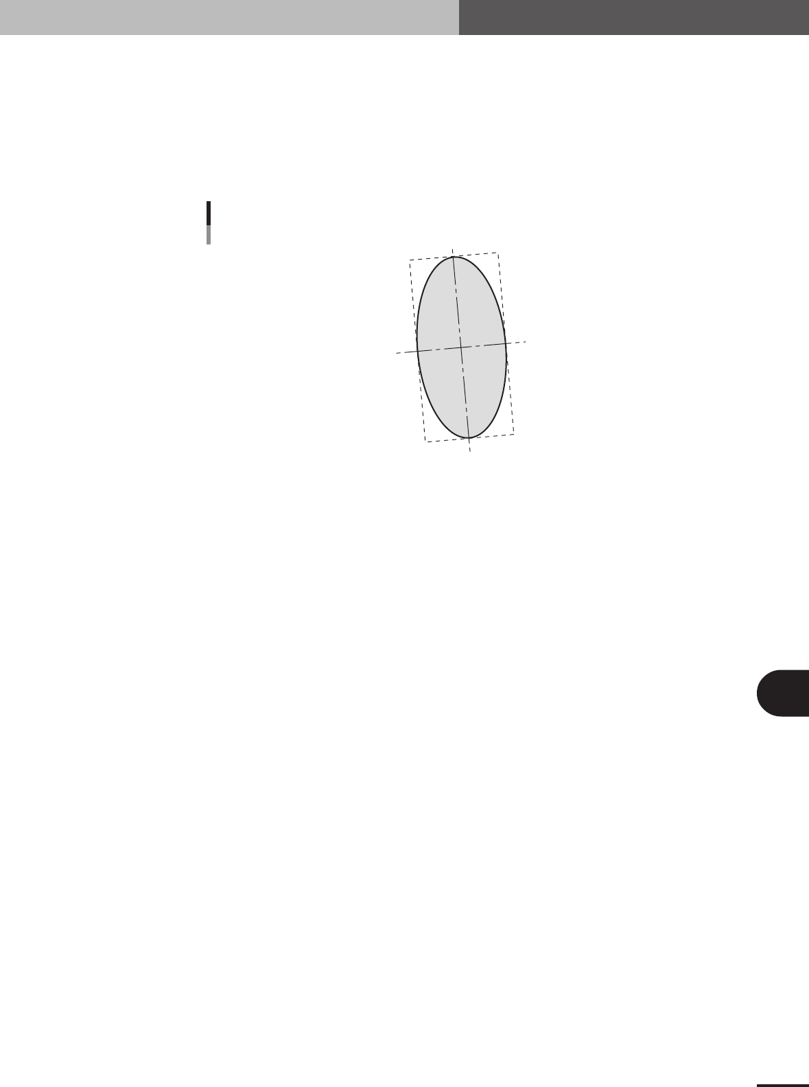
1. Alignment Type: AsMark (components comprised of 1 section)
Algorithm for recognizing components comprised of 1 section with a shape as shown below. This
algorithm is used for recognizing irregular shaped components. The component center is the
center-of-gravity position and the tilt is the main axis tilt. So the tilt cannot be found for circular or
square components since these have no main axis.
C
Alignment Type : Mark
23B02-5E-20
■ Mark type components
Alignment Group Special
Alignment Type AsMark
Comp. Threshold Set the binary level. (If set to 0, the binary level is set
automatically.)
Comp. Tolerance Set the shape dimension tolerance.
Search Area Set the detection range.
Body Size X Set the component size.
Body Size Y Set the component size.
Body Size Z Set the component thickness.
Surface Type Select "Reflect" (reflective surface) or "NonReflect" (mat
surface). If component appears whitish, select "Reflect".
Select "NonReflect" if component does not appear whitish.
Cut Outer Noise Select from 0 to 7.
Cut Inner Noise Select from 0 to 7.
Noise Cut Order Select "Inner" or "Outer".
B -12
B
Alignment Type glossary
2. Alignment Type glossary
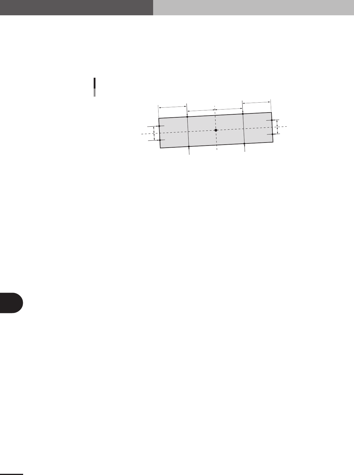
2. Algorithm: Special 1 (Components with 1 shape)
Component center and tilt are detected utilizing several lines.
The overall center-of-gravity and tilt of the component are found as a feature amount. Lines 1 and
2 are set based on this feature amount and the edge positions P1 to P4 found on those lines. The tilt
of line 3 connecting the center points of P3 and P4 and the center points of P1 and P2 is taken as
the component tilt. Lines 5, 6, 7 and 8 are set in parallel with line 3 and edge positions P5 to P8
found. The component center is found by taking the average of these points.
P1
P7
P8
P5
P6
P2
G
P3
P4
Line 3
Line 4
Line 1
Line 2
Line 7
Line 8
Line 5
Line 6
Mark: Special 1
23B03-5E-20
■ Special components (Special: AsMark)
Alignment Group Special
Alignment Type Special
Comp. Threshold Set the binary level. (If set to 0, the binary level is set
automatically.)
Comp. Tolerance Specify the shape dimension tolerance.
Search Area Set the detection range.
Body Size X Set the component size.
Body Size Y Set the component size.
Body Size Z Set the component thickness.
Algorithm Special 1
Base Alignment AsMark
Vision Option 1 Set the detection direction. 0: Auto, 1: Left side/upper side
only, 2: Right side/lower side only, 3: Both sides
When set to 0 (Auto), the component is not detected in the
direction where it crosses the frame of the search window.
Vision Option 2 Set to 0.
Vision Option 3 Set to 0.
Vision Option 4 Specify a numeric value representing the Cut Inner Noise
and Cut Outer Noise levels, and also the sequence to
execute them. For example, when the Cut Outer Noise
level is set as n1 and the Cut Inner Noise level is set as n2,
set a value of "n2 × 8 + n1" here. When executing in the
sequence from Cut Outer Noise to Cut Inner Noise, set a
value obtained by subtracting 128 from "n2 × 8 + n1".
Lead Group W When this parameter is set to 0 or 10, a line 1 is
automatically set at a position 1/4th of the detection length
from the center-of-gravity. Lines 7 and 8 are set at a
position 1/4th of the detection width.
Lead Number W1 (mm) Set to 0.
ReflectLL W1 (mm) Set to 0.
Lead Width W1 (mm) Set to 0.
Lead Pitch W1 (mm) Set to 0.
Find PosX W1 (mm) Enter a numeric value to set the detection position. When
Lead Group is 1, line 1 is set to a position offset by this
value from the edge position.
Find PosY W1 (mm) Enter a numeric value to set the detection positions. When
Lead Group is 1, lines 7 and 8 are set to positions offset by
this value from line 3.