M3plus_OperationManual_e.pdf - 第228页
B - 15 B Alignment T ype glossar y 2. Alignment T ype glossar y 4. Algorithm: Special 3 (Component with shape consisting of 4 sec- tions) Find the center-of-gravity positions G1 to G4 for the 4 sections. Find P1 to P8 th…
B -14
B
Alignment Type glossary
2. Alignment Type glossary
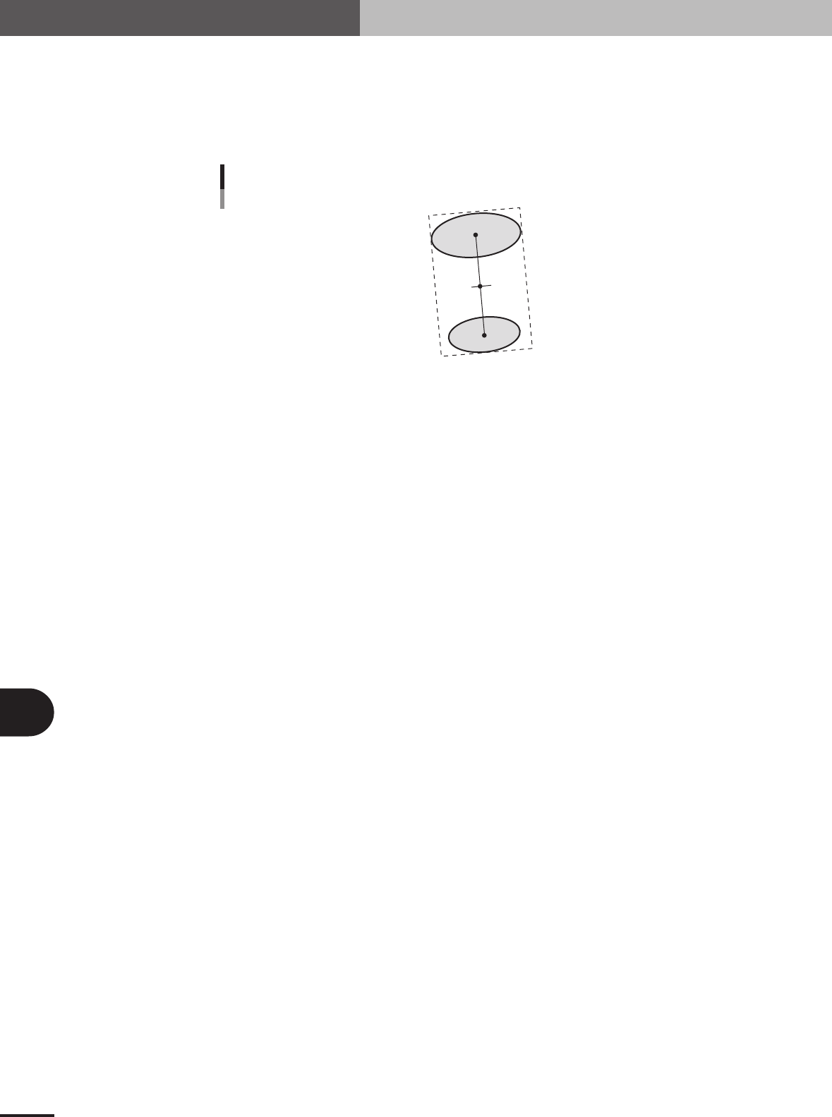
3. Algorithm: Special 2 (Component with shape consisting of 2 sec-
tions)
This is useful when the component is divided into 2 sections as shown below.
The center position is an average of center-of-gravity of each section. The tilt is found from the tilt
of the direct line joining the center-of-gravity positions of the 2 sections.
C1
C2
Alignment Type : Mark
23B04-5E-20
■ Component shape consisting of 2 sections (AsMark)
Alignment Group Special
Alignment Type Special
Comp. Threshold Set the binary level. (If set to 0, the binary level is set
automatically.)
Comp. Tolerance Set the shape dimension tolerance.
Search Area Set the detection range.
Body Size X Set the component size.
Body Size Y Set the component size.
Body Size Z Set the component thickness.
Surface Type Select "Reflect" (reflective surface) or "NonReflect" (mat
surface).
Algorithm Special 2
Base Alignment AsMark
Vision Option 1 Set to 0.
Vision Option 2 Set to 0.
Vision Option 3 Set to 0.
Vision Option 4 Specify a numeric value representing the Cut Inner Noise
and Cut Outer Noise levels, and also the sequence to
execute them. For example, when the Cut Outer Noise
level is set as n1 and the Cut Inner Noise level is set as n2,
set a value of "n2 × 8 + n1" here. When executing in the
sequence from Cut Outer Noise to Cut Inner Noise, set a
value obtained by subtracting 128 from "n2 × 8 + n1".
Lead Group N Set to 1.
Lead Number N1 Set to 1.
ReflectLL N1, Lead Width N1 Set the size (surface area) of the upper section. If a
rectangle, specify a value of the lead length multiplied by
the lead width. If a circle, specify the diameter of the circle
with the lead width and a lead length equal to 0.
Lead Pitch N1 Set to 0.
Find PosX N1, Find PosY N1 Set the center-of-gravity position of the upper section.
Lead Group S Set to 1.
Lead Number S1 Set to 1.
ReflectLL S1, Lead Width S1 Set the size (surface area) of the lower section. If a
rectangle, specify a value of the lead length multiplied by
the lead width. If a circle, specify the diameter of the circle
with the lead width and a lead length equal to 0.
Lead Pitch S1 Set to 0.
Find PosX S1, Find PosY S1 Set the center-of-gravity position of the lower section.
Others Set to 0.
B -15
B
Alignment Type glossary
2. Alignment Type glossary
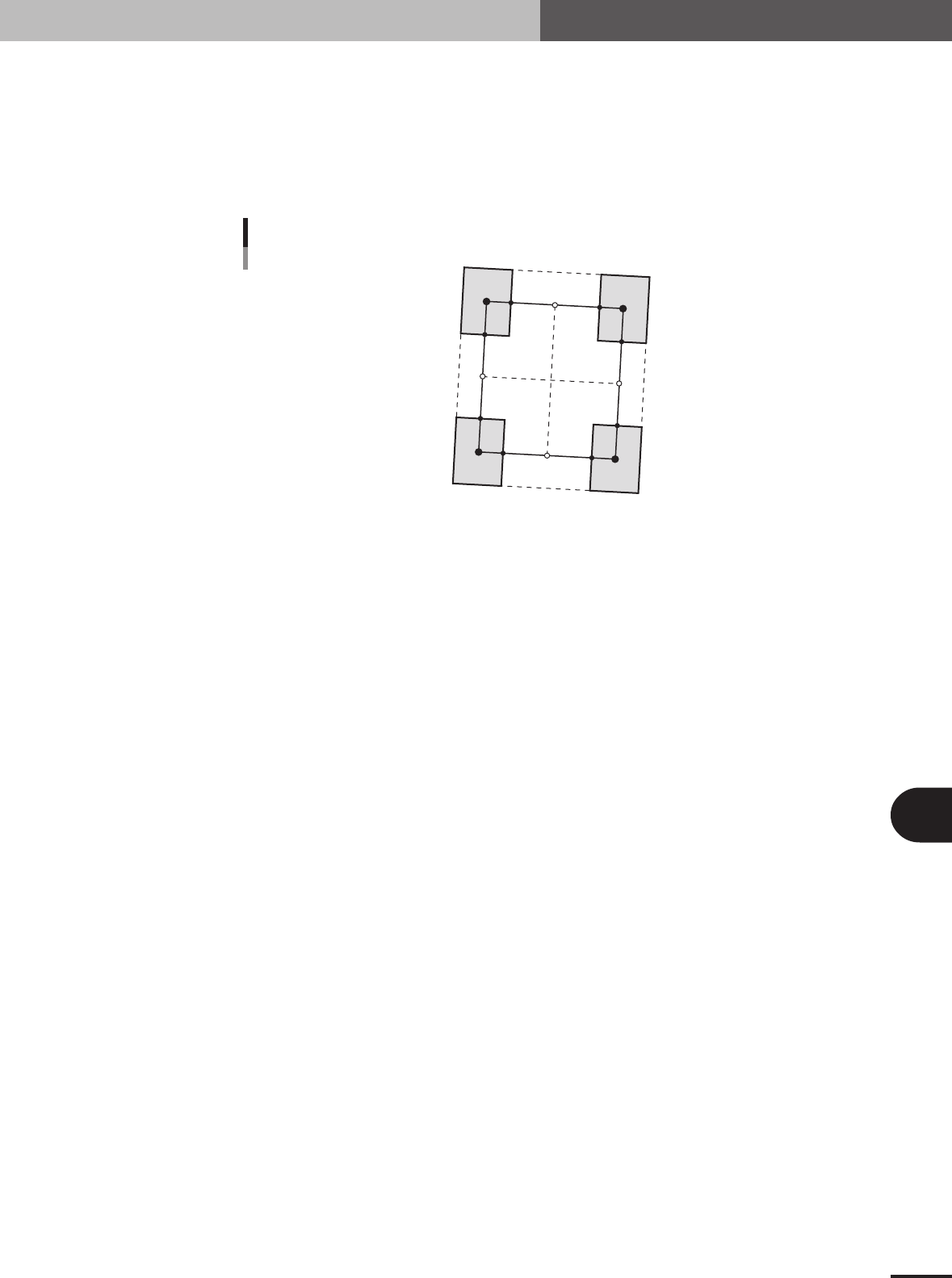
4. Algorithm: Special 3 (Component with shape consisting of 4 sec-
tions)
Find the center-of-gravity positions G1 to G4 for the 4 sections. Find P1 to P8 that connect those
center-of-gravity positions by straight lines. The component center is the intersection (cross point)
of the lines joining the side center found from P1 and P2, and the side center found from P3 and
P4; and the line joining the side center found from P5 and P6 and the side center found from P7
and P8. The component tilt is found from the tilt of 2 lines.
P
1
P5
G1
G3
G2
G4
P6
P7
P8
P2
P3
P4
Mark: Special 3
23B05-5E-20
■ Component consisting of 4 sections (AsMark)
Alignment Group Special
Alignment Type Special
Comp. Threshold Set the binary level. (If set to 0, the binary level is set
automatically.)
Comp. Tolerance Set the shape dimension tolerance.
Search Area Set the detection range.
Body Size X Set the component size.
Body Size Y Set the component size.
Body Size Z Set the component thickness.
Surface Type Select "Reflect" (reflective surface) or "NonReflect" (mat
surface).
Algorithm Special 3
Base Alignment AsMark
Vision Option 1 Set to 0.
Vision Option 2 Set to 0.
Vision Option 3 Set to 0.
Vision Option 4 Specify a numeric value representing the Cut Inner Noise
and Cut Outer Noise levels, and also the sequence to
execute them. For example, when the Cut Outer Noise
level is set as n1 and the Cut Inner Noise level is set as n2,
set a value of "n2 × 8 + n1" here. When executing in the
sequence from Cut Outer Noise to Cut Inner Noise, set a
value obtained by subtracting 128 from "n2 × 8 + n1".
Lead Group N Set to 1.
Lead Number N1 Set to 2.
ReflectLL N1 Set the lead length of the upper leads.
Lead Width N1 Set the lead width of the upper leads.
Lead Pitch N1 Set the upper lead pitch.
Find PosX N1, Find PosY N1 Set the center-of-gravity position of the upper leads.
Lead Group S Set to 1.
Lead Number S1 Set to 2.
ReflectLL S1 Set the lead length of the lower leads.
Lead Width S1 Set the lead width of the lower leads.
Lead Pitch S1 Set the lower lead pitch.
Find PosX S1, Find PosY S1 Set the center-of-gravity position of the lower left lead.
Others Set to 0.
B -16
B
Alignment Type glossary
2. Alignment Type glossary
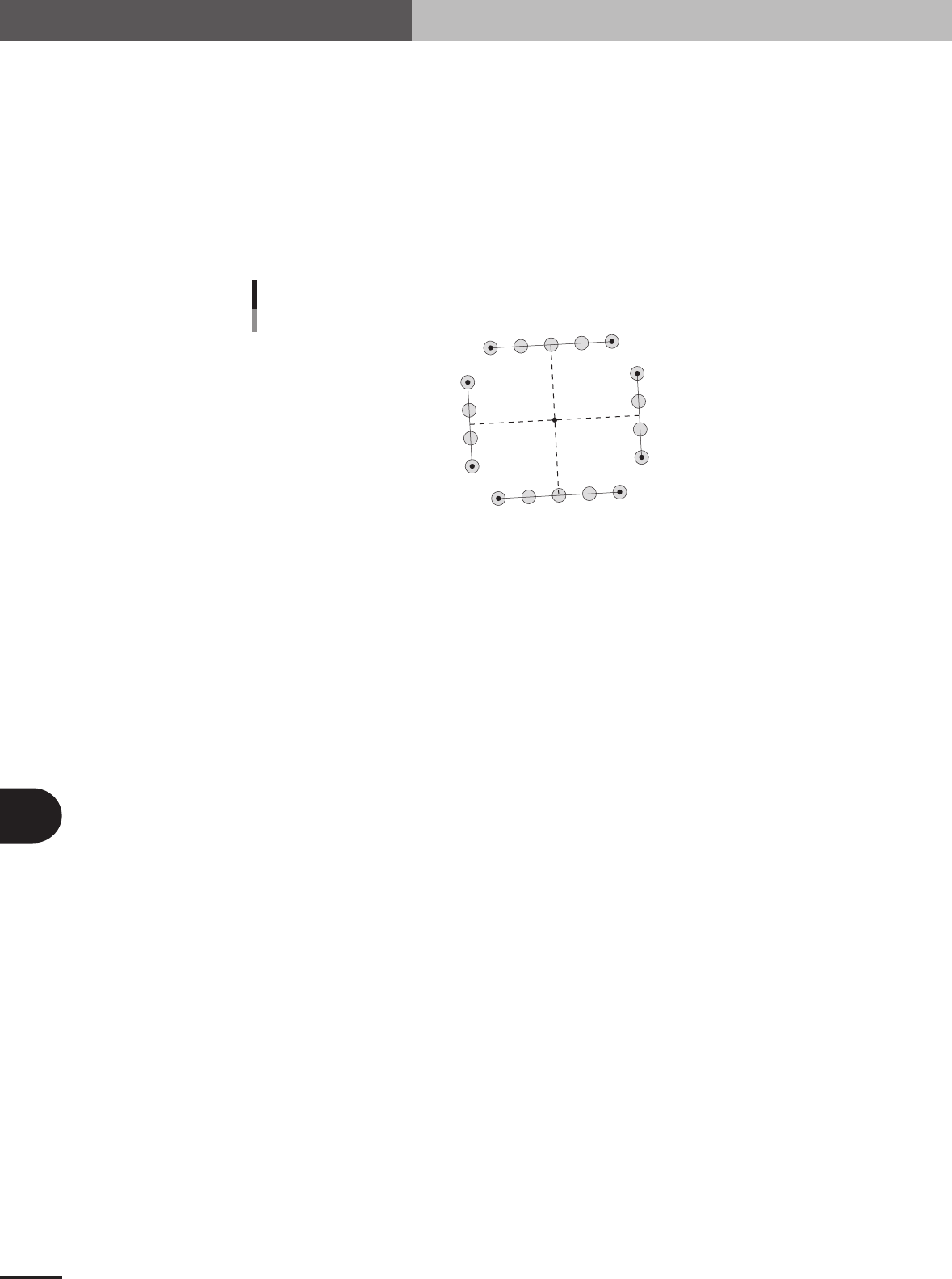
5. Algorithm: Special 4 (Component consisting of multiple sections)
Finds the center of each side and finds the component tilt from the lines joining those side centers.
Algorithm can be used when there are leads on the bottom only, left only, right only, top and
bottom, left and right, top and lower left, top and lower right, upper left and right, lower left and
right, top bottom left and right.
Several methods can be selected to find the component center.
When Option 2 is 0, the center of a circumscribed rectangle is taken as the component center.
When Option 2 is 1, the rectangle center found from lines running from the center of each side is
taken as the component center.
When Option 2 is 2, the average center point of the detected leads is taken as the component
center.
P1
P5
P6
P7
C
P8
P2
P3
P4
Mark: Special 4
23B06-5E-20
■ Component consisting of multiple sections (AsMark)
Alignment Group Special
Alignment Type Special
Comp. Threshold Set the binary level. (If set to 0, the binary level is set
automatically.)
Comp. Tolerance Set the shape dimension tolerance.
Search Area Set the detection range.
Body Size X Set the component size.
Body Size Y Set the component size.
Body Size Z Set the component thickness.
Surface Type Select "Reflect" (reflective surface) or "NonReflect" (mat
surface).
Algorithm Special 4
Base Alignment AsMark
Vision Option 1 Set to 0.
Vision Option 2 Set to 0.
Vision Option 3 Set to 0.
Vision Option 4 Specify a numeric value representing the Cut Inner Noise
and Cut Outer Noise levels, and also the sequence to
execute them. For example, when the Cut Outer Noise
level is set as n1 and the Cut Inner Noise level is set as n2,
set a value of "n2 × 8 + n1" here. When executing in the
sequence from Cut Outer Noise to Cut Inner Noise, set a
value obtained by subtracting 128 from "n2 × 8 + n1".
Lead Group N Set the number of lead groups (1 or 2).
Lead Number N1 Set the number of leads.
ReflectLL N1, Lead Width N1 Set the size (surface area) of the upper lead section. If a
rectangle, specify a value of the lead length multiplied by
the lead width. If a circle, specify the diameter of the circle
with the lead width and a lead length equal to 0.
Lead Pitch N1 Set the pitch of the upper lead section.
Find PosX N1, Find PosY N1 Set the center-of-gravity position of the upper left lead
section.
Lead Number N2 to Find PosY N2 Set the group 2 data when the number of lead groups is 2.
Set 0 when the number of lead groups is 1.
Lead Group S Set the number of lead groups (1 or 2).