M3plus_OperationManual_e.pdf - 第24页
1 P art names and functions 1 - 3 2. Operation panel and data input units Standard machines are equipped with an operation display, operation panel buttons, a keyboard and a mouse on the front of the machine, to operate …
1 -2
1
Part names and functions
1. Main unit
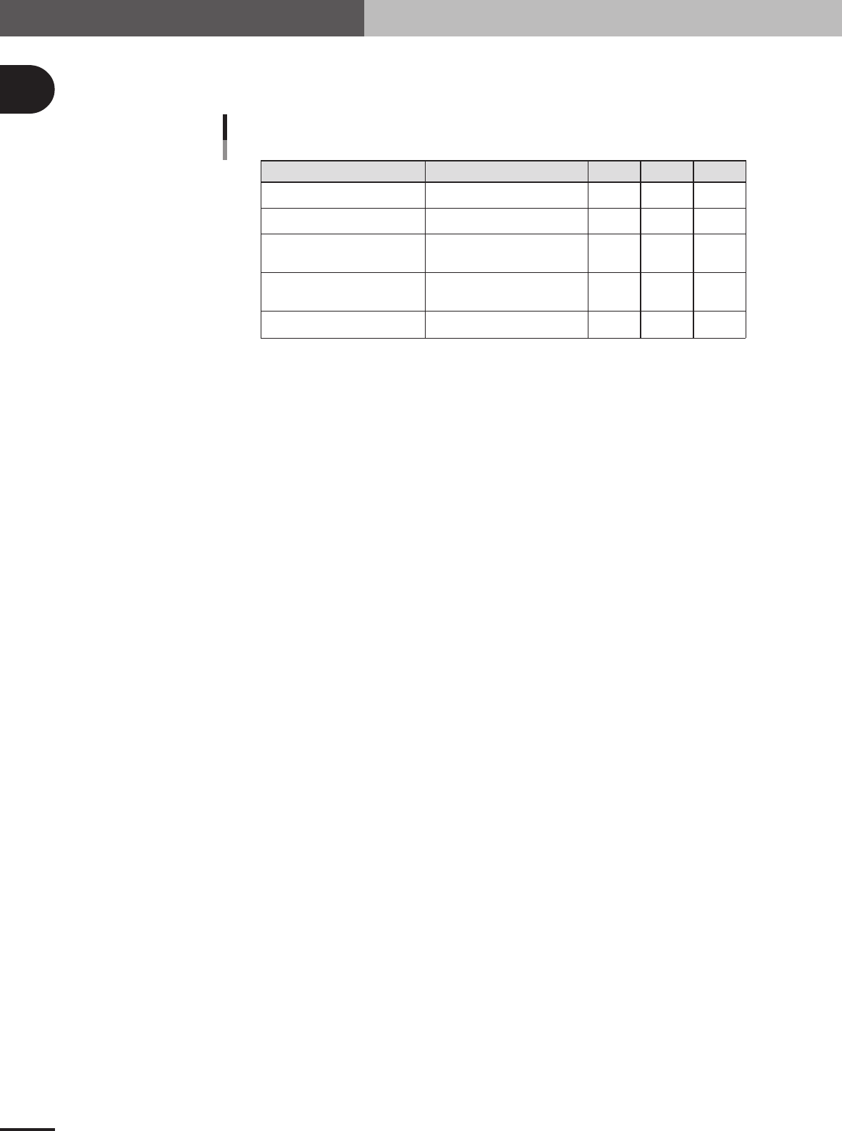
Signal light
Indicates current operating conditions of the mounter with a green, yellow and red light explained
below.
Warm-up or automatic operation
Emergency stop
System error
(with buzzer ON)
Operation or PCB data error
(with buzzer ON)
Components cannot be used.
ON
-----
-----
-----
-----
-----
ON
ON
-----
-----
-----
-----
-----
ON
Flashing
Excessive current
Secondary limit over
Pickup error, recognition error
Data check error, etc.
Components run out, etc.
Machine status Example Green Red Yellow
Signal light
25105-5E-20
Alarm buzzer
The signal light has a built-in buzzer that buzzer sounds if an error or abnormal operation occurs.
(Volume can be adjusted by turning right or left.)
Safety cover
This cover must be closed during operation. If opened, emergency stop is triggered.
Pressure indicator (left side)
See "1.1 Air regulator unit" in Appendix.
Head assembly
Picks up and mounts components with the nozzles at the tip. Also has a camera for recognizing
marks on PCB. (See "3. Head assembly" in this chapter.)
Front panel
Installed behind this panel are the system mother board, power supply board, servo control board,
vision board and CD-ROM drive. The main power connection terminals and beakers are also located
here. Keep this panel closed during operation.
Power switch
Turns on or off power to machine.
I/O signal connectors (inside front panel)
See "1.2 Connection between machines" in Appendix.
Feeder plate
See "4. Feeder plate section" in this chapter.
1
Part names and functions
1 -3
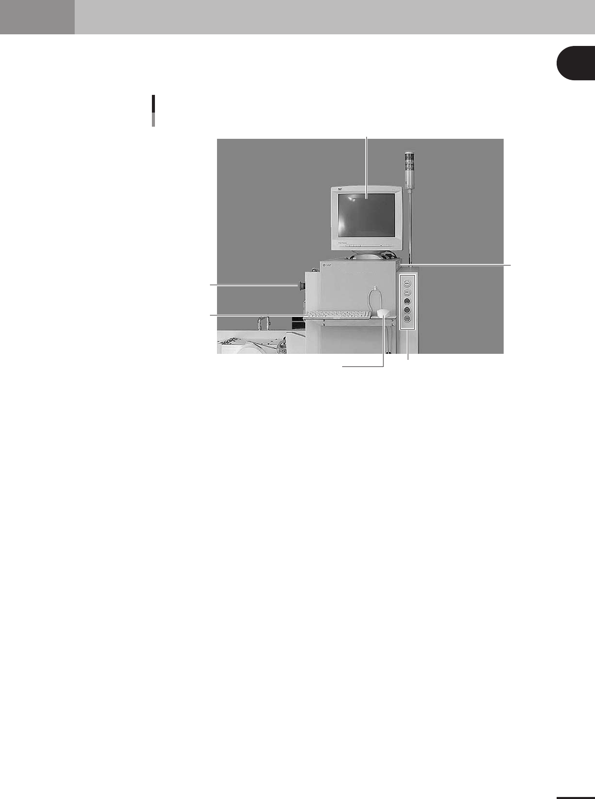
2. Operation panel and data input units
Standard machines are equipped with an operation display, operation panel buttons, a keyboard and a
mouse on the front of the machine, to operate the machine and make data settings. The functions of
these units are explained below.
Operation display
Mouse
Keyboard
Operation panel button
FD drive
Operation panel and data input unit
EMERGENCY
STOP button
23102-5E-20
1 -4
1
Part names and functions
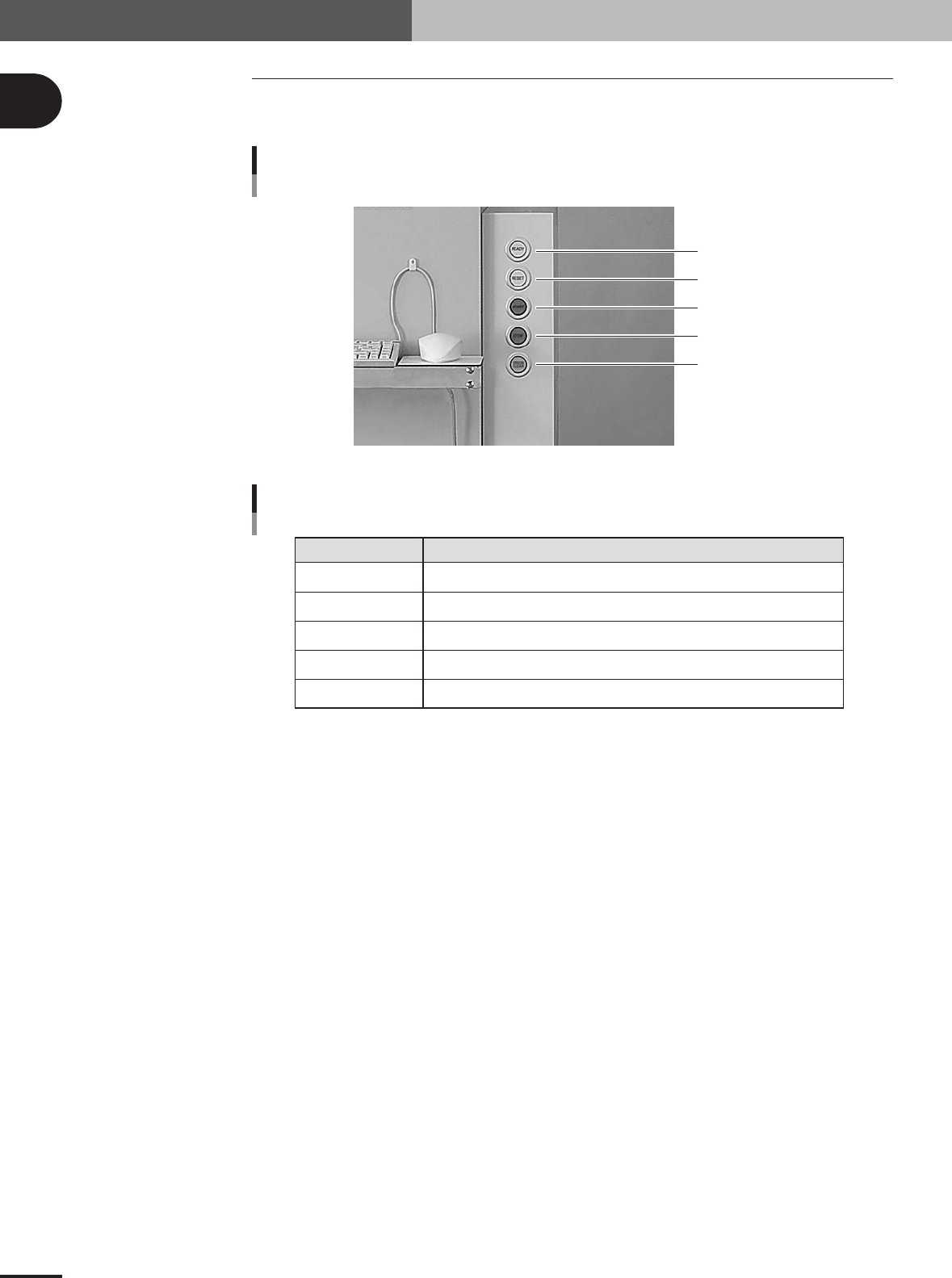
2.1 Operation panel buttons
The operation panel buttons are provided on the front of the machine to run major com-
mands frequently used to operate the machine.
READY
RESET
START
STOP
ERROR CLEAR
Operation panel buttons
23103-5E-20
READY
RESET
START
STOP
ERROR CLEAR
Release emergency stop and turn the servo on.
Stop automatic operation and return to standby for PCB production.
Perform component mount according to PCB data.
Interrupt automatic operation. (Press START to resume operation.)
Stop buzzer sound and clear error screen.
Button name Use the button to:
Operation panel button functions
25102-5E-20
2. Operation panel and data input units