M3plus_OperationManual_e.pdf - 第242页
1 P art names and functions 1 - 1 1. Par t names and functions This section describes major part names and functions of the tray shuttle feeder (hereafter called "TSF1"). 1.1 TSF1 main unit Upper safety co ver …
1
Part names and functions
1 -1
1. Part names and functions
This section describes major part names and functions of the tray shuttle feeder (hereafter called
"TSF1").
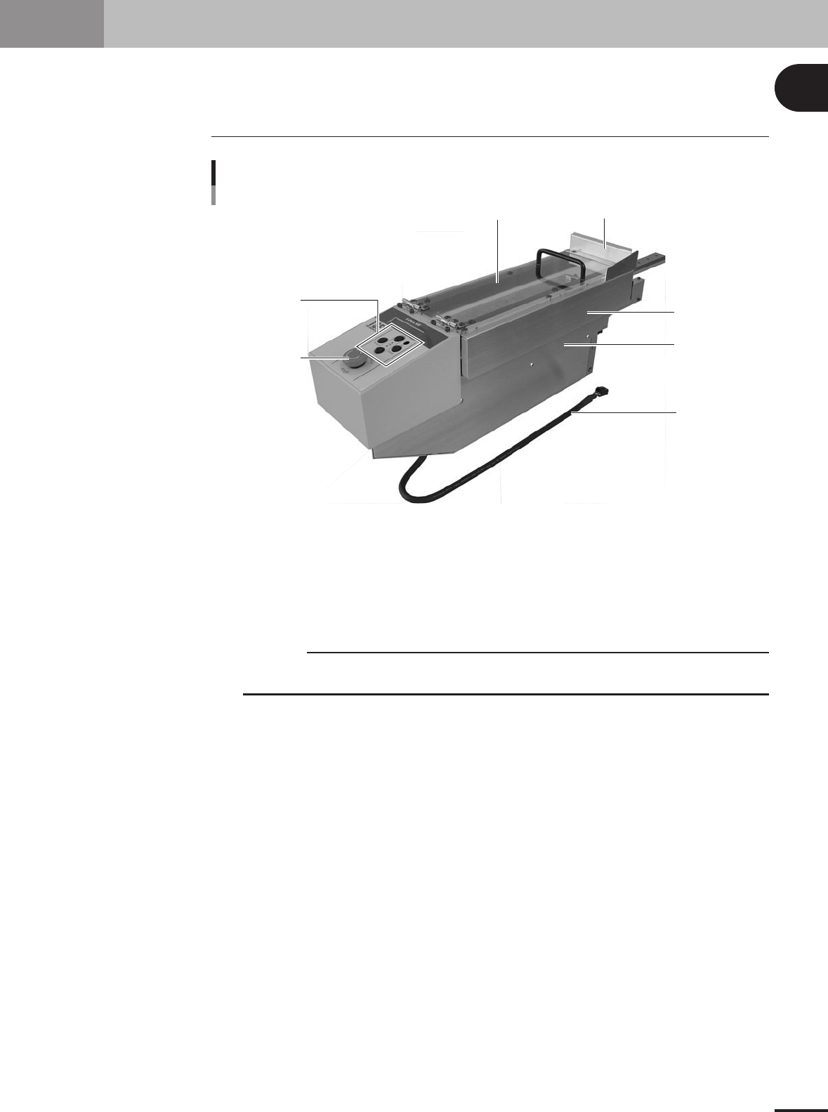
1.1 TSF1 main unit
Upper safety cover Feeder cover
Operation switch
panel
Emergency stop
button
Side safety cover 1
Side safety cover 2
Signal cable
TSF1 main body 1
73100-5V-00
Operation switch panel
Use the button switches on this panel to return the shuttle to its origin position, move it to the tray
replacement position or perform JOG operation.
Upper safety cover
Open this cover to set up a tray on the TSF1.
c
CAUTION
Do not apply force to the upper safety cover or place any object on it. Doing so might deform or
damage the cover.
Feeder cover
This is attached to the end of the upper safety cover, to prevent you from putting your hands or other
objects inside the mounter.
Side safety cover 1
When two TSF1 units are used, you must remove this side safety cover of the TSF1 that is installed
in position 1.
Side safety cover 2
When two TSF1 units are used, you must also remove this side safety cover of the TSF1 that is
installed in position 1.
Signal cable
Connect this signal cable to the mounter (M CUBE PLUS). Always turn off the mounter power
switch before plugging this signal cable into the connector on the mounter side or unplugging it.
Emergency stop button
When pressed, this button immediately turns off the servo control to stop the TSF1 and mounter. To
cancel emergency stop, release this button and then press the [READY] button on the mounter.
1 -2
1
Part names and functions
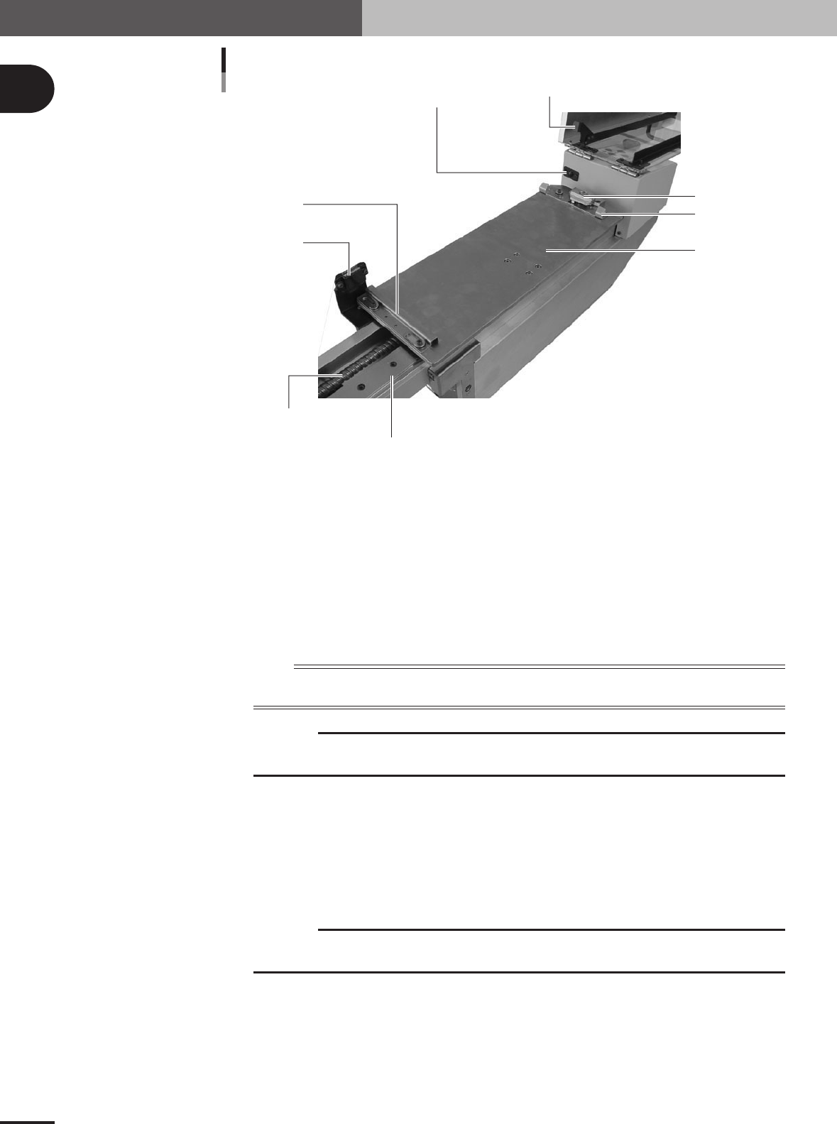
Cover safety switch
Safety switch push plate
Tray guide F
Magnet catch
Hold knob
Top plate
TSF1 main body 2
Tray guide R
Shuttle axis linear guide
Shuttle axis ball screw
73101-5V-00
Tray guide F
Holds the forward edge (mounter side) of the tray when placed on the top plate.
Top plate
This plate moves along the shuttle axis to convey the tray clamped on the plate.
Tray guide R
Holds the rear edge (TSF1 operation panel side) of the tray when placed on the top plate.
Hold knob
Use this knob to clamp the tray on the top plate.
n
NOTE
The shuttle is an assembly consisting of the top plate, tray guides F and R and the hold knob. The shuttle moves
back and forth along the shuttle path (axis).
c
CAUTION
Do not hold the shuttle section when carrying the TSF1 or installing to the mounter. Doing so
might cause the TSF1 to malfunction.
Magnet catch
Keeps the upper safety cover closed.
Shuttle axis ball screw
Moves the shuttle along the shuttle axis.
Shuttle axis linear guide
The shuttle moves along this linear guide.
c
CAUTION
Do not hold the linear guide or apply shock to the linear guide when carrying the TSF1 or
installing to the mounter. Doing so might cause the TSF1 to malfunction.
Cover safety switch
This is the interlock switch for the upper safety cover. When the upper safety cover is opened, this
switch triggers emergency stop (servo control OFF).
Safety switch push plate
When the upper safety cover is closed, this push plate activates the cover safety switch so the
mounter detects that the upper safety cover is closed.