M3plus_OperationManual_e.pdf - 第247页
2 - 2 2 Ho w to handle and operate the TSF1 2 Connect the signal cable. Unplug the shorting connector (LC2-M51FK-XXX) from the feeder plate connector located under the feeder position where you are gong to install the TS…
2
How to handle and operate the TSF1
2 -1
2. How to handle and operate the TSF1
This section explains how to install the TSF1 to the mounter and remove it from the mounter, as well
as setups for tray components.
2.1 Installing the TSF1
n
NOTE
Up to two TSF1 units can be installed in two positions (positions 1 and 2) on the feeder plate of the mounter (M
CUBE PLUS). However, each TSF1 unit is shipped with the single use setups. Therefore, when using two TSF1
units, you must change the setups (safety cover and magnet catch attachment methods) and also remove the
feeder plate safety hoods and tape guide plates of the mounter. (For details on how to change the TSF1 and
mounter setups, see Chapter 3, "Setup". When only one TSF1 is used, it must be installed in position 1. (For
safety reasons, the TSF1 cannot be installed only in position 2.)
w
WARNING
ALWAYS TURN OFF THE MOUNTER POWER SWITCH BEFORE INSTALLING OR REMOVING
THE TSF1. INSTALLING OR REMOVING THE TSF1 WHILE THE POWER IS TURNED ON MIGHT
CAUSE THE TSF1 TO MALFUNCTION.
1
Install the TSF1 on the feeder plate.
Carefully install the TSF1 on the feeder plate by simultaneously inserting the three
positioning pins into the specified positioning holes and by pushing the TFS1 body
until it is automatically locked by the clamp.
Positioning pin insertion position
Position 1
Position 2
TSF1 position Positioning pin
L
C
R
L
C
R
1
3
5
8
10
12
Feeder plate No.
75103-5V-00
w
WARNING
DO NOT APPLY EXCESSIVE FORCE TO THE SHUTTLE DRIVE PARTS SUCH AS THE LINEAR
GUIDE. APPLYING EXCESSIVE FORCE TO THE DRIVE PARTS MIGHT CAUSE THE TSF1 TO
MALFUNCTION.
2 -2
2
How to handle and operate the TSF1
2
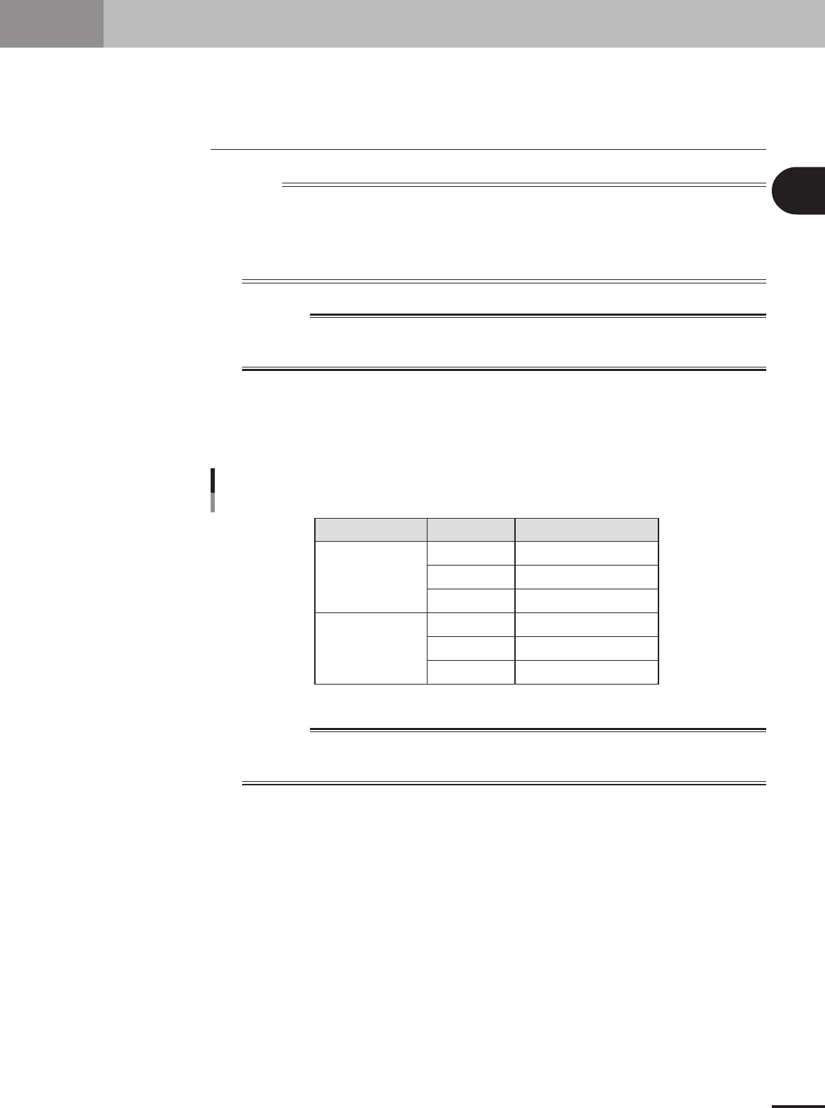
Connect the signal cable.
Unplug the shorting connector (LC2-M51FK-XXX) from the feeder plate connector
located under the feeder position where you are gong to install the TSF1. Then plug in
the TSF1 signal cable connector.
Short connector and signal connector
Shorting connector
Signal cable
For position 1
For position 2
73200-5V-00
c
CAUTION
Shorting connectors are connected by a nylon tie to the side panel of the feeder plate. After
unplugging a shorting connector, leave it connected to the side panel of the feeder plate to
avoid losing it.
3
Start the mounter and TSF1.
Use the following steps to start the mounter and TSF1.
1. Make sure the safety covers for the mounter and TSF1 are all closed.
2. Release the emergency stop button on the TSF1.
3.Start the mounter. (The TSF1 will also start automatically.)
4.Return the mounter to the origin position. (The TSF1 will also return to its origin
position.)
2 -3
2
How to handle and operate the TSF1
2.2 Setting up the component tray
1
Open the TSF1 upper safety cover.
After pressing the emergency stop button on the TSF1, open the TSF1 upper safety
cover.
2
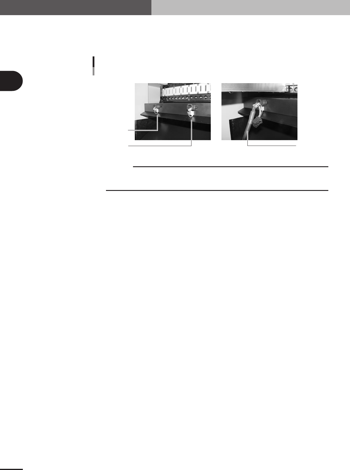
Release the hold knob.
Turn the hold knob to the release position.
Releasing the hold knob
Release position
Hold position
73201-5V-00
3
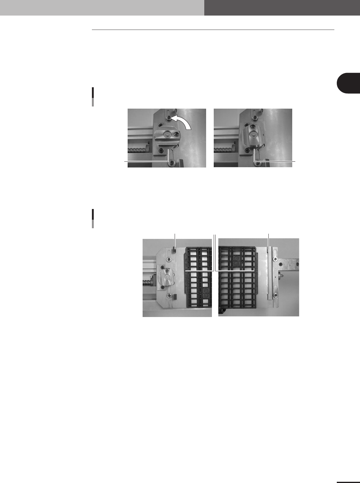
Adjust the tray guide positions.
Slide the tray guides F and R right or left so that they align with the protruding edges
of the tray.
Tray guide alignment
Tray protruding edge
Tray guide F
Tray guide R
73202-5V-00
e