M3plus_OperationManual_e.pdf - 第254页
3 Setup 3 - 1 3. Setup When installing the TSF1 on the feeder plate of the mounter (M CUBE PLUS), you must adjust the TSF1 safety cover and change the ID setting, depending on the number of TSF1 units to be used and the …
2 -8
2
How to handle and operate the TSF1
2.5 Production
The basic procedure for production using the TSF1 is explained below.
n
NOTE
For information about how to create tray component data, refer to Chapter 3, "Creating the PCB data", in the M
CUBE PLUS operation manual.
1
Set the component tray on the shuttle of the TSF1.
1.To continue the previous production, start it without resetting the component
count. (The component count is stored in memory.) When you use a new tray and
want to reset the component count, press the [TrayCnt] button on the Setup screen
and clear the component count.
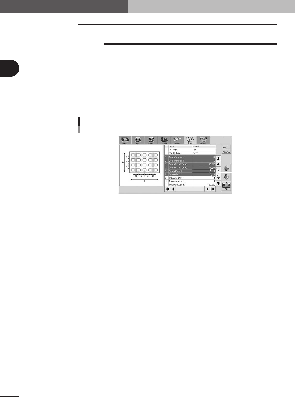
2.If you want to start picking up a component from the specified position on the tray,
open the [Parts]-[Tray] tab and, in the "Current Pos. X" and "Current Pos. Y" fields,
set the position from which to start picking up a component.
Current Pos. XY
Current Pos. XY
77206-5V-00
2
Start the production.
1.The production starts by picking up the components from the component count
position that was stored in memory when the previous production ended or from
the newly specified position on the tray.
2.When the last component has been picked up, a "tray empty error" is issued and
the mounter stops while the last component is still picked up by the head. The
shuttle then automatically moves to the tray replacement position and production is
temporarily stopped.
3
Replace the component tray.
After pressing the emergency stop button on the TSF1, open the upper safety cover
and replace the component tray with a new one.
4
Resume the production.
Close the upper safety cover and release the emergency stop button. Then press the
[READY] button on the mounter to reset the emergency stop and press the [START]
button to resume production. The component count is cleared automatically.
n
NOTE
If you want to finish the production after mounting the tray component that was last picked up (without replacing
the tray), follow the steps below.
1.A "tray empty error" is issued when the last tray component has been picked up.
2.Press the [ERROR CLEAR] button on the mounter.
3.Press the [START] button to resume production.
4.The last tray component is mounted on the PCB. In this case, a component pickup
error will occur in the next pickup cycle because the component count is
automatically cleared.
e
3
Setup
3 -1
3. Setup
When installing the TSF1 on the feeder plate of the mounter (M CUBE PLUS), you must adjust the
TSF1 safety cover and change the ID setting, depending on the number of TSF1 units to be used and
the installation position. It is also necessary to remove the feeder plate safety hoods and tape guide
plates of the mounter according to the number of TSF1 units to be used. This section explains how to
change these TSF1 and mounter setups.
n
NOTE
Each TSF1 unit is always shipped with the single use setups (specifications A). The mounter is also shipped with
the setups that do not use TSF1 (all the feeder safety hoods and tape guide plates are attached).
c
CAUTION
1. Under the feeder plate, there are two connectors for connection to the TSF1 signal cable.
Since the mounter is shipped with shorting connectors plugged into these connectors, you
must unplug the shorting connector when using the TSF1. However, leave the shorting
connector plugged into the connector in the position where you are not going to install the
TSF1. If you unplug the shorting connector at the position where the TSF1 is not installed and
start the mounter operation, emergency stop will be triggered.
2. For safety reason, position 2 can not be used when only 1 TSF1 unit is installed.
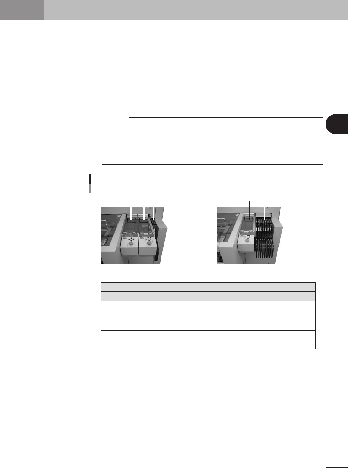
Changing the TSF1 setup
Position 1 Position 2
One TSF1 unit and nine 8mm feedersTwo TSF1 units and two 8mm feeders
8mm feeders x 2 8mm tape feeders x 9
Position 1
Position 1
Position 2
Feeder plate safety hoods of mounter
Tape guide plate
Shorting connector
Note 1: For safety reason, position 2 can not be used when only 1 TSF1 unit is installed.
1 unit
Specifications A
Cannot be installed (Note 1)
Uses Nos. 2 and 3.
Uses Nos. 2 and 3.
Use at position 2.
2 units
Specifications B
Specifications C
Uses No. 3
Uses No. 3
Not used
Not used
--
--
Uses Nos. 1, 2 and 3
Uses Nos. 1, 2 and 3
Uses at positions 1 and 2
Number of TSF1 units / Installation position
73300-5V-00
3 -2
3
Setup
3.1 Changing the TSF1 setups
w
WARNING
ALWAYS TURN OFF THE MOUNTER POWER SWITCH BEFORE CHANGING THE TSF1 SETUPS.
CHANGING THE SETUPS WHILE THE POWER IS TURNED ON MIGHT CAUSE AN ACCIDENT OR
FAULTY OPERATION.
3.1.1 Changing the setups: from specifications A to B
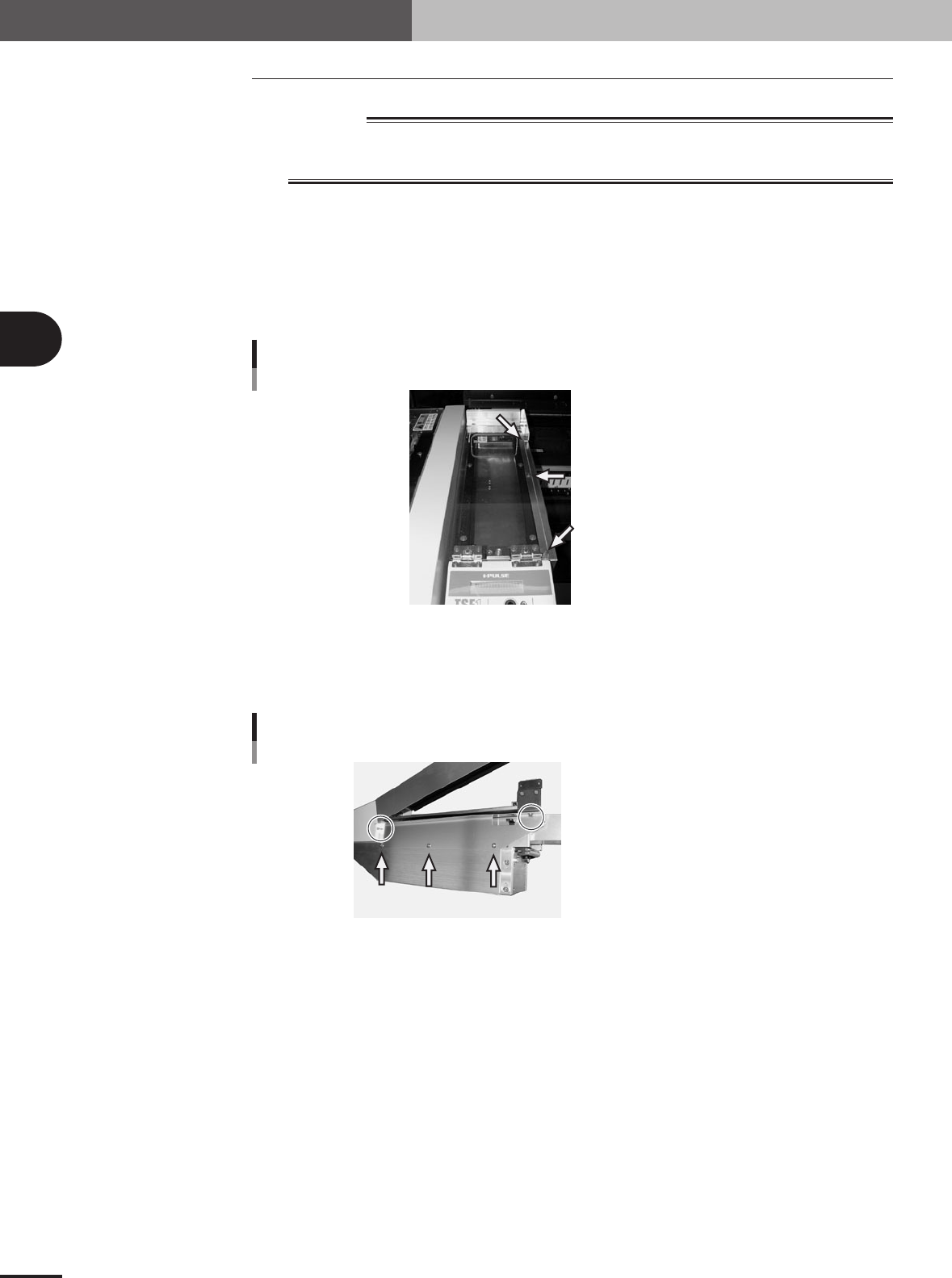
1
Remove the side safety cover 1.
Remove the three screws holding the side cover 1 and remove the side cover 1 from
the upper safety cover.
Set screw with washer (x 3)
Side safety cover 1
73301-5V-00
2
Remove the side safety cover 2.
Remove the five screws holding the side cover 2 and remove the side cover 2 from
the TSF1 main body.
Shown in circle: Set screw (x 2)
Pointed by arrow: Binding screw (x 3)
Side safety cover 2
73302-5V-00