M3plus_OperationManual_e.pdf - 第255页
3 - 2 3 Setup 3.1 Changing the TSF1 setups w WARNING ALWAYS TURN OFF THE MOUNTER POWER SWITCH BEFORE CHANGING THE TSF1 SETUPS. CHANGING THE SETUPS WHILE THE POWER IS TURNED ON MIGHT CAUSE AN ACCIDENT OR FAULTY OPERATION.…
3
Setup
3 -1
3. Setup
When installing the TSF1 on the feeder plate of the mounter (M CUBE PLUS), you must adjust the
TSF1 safety cover and change the ID setting, depending on the number of TSF1 units to be used and
the installation position. It is also necessary to remove the feeder plate safety hoods and tape guide
plates of the mounter according to the number of TSF1 units to be used. This section explains how to
change these TSF1 and mounter setups.
n
NOTE
Each TSF1 unit is always shipped with the single use setups (specifications A). The mounter is also shipped with
the setups that do not use TSF1 (all the feeder safety hoods and tape guide plates are attached).
c
CAUTION
1. Under the feeder plate, there are two connectors for connection to the TSF1 signal cable.
Since the mounter is shipped with shorting connectors plugged into these connectors, you
must unplug the shorting connector when using the TSF1. However, leave the shorting
connector plugged into the connector in the position where you are not going to install the
TSF1. If you unplug the shorting connector at the position where the TSF1 is not installed and
start the mounter operation, emergency stop will be triggered.
2. For safety reason, position 2 can not be used when only 1 TSF1 unit is installed.
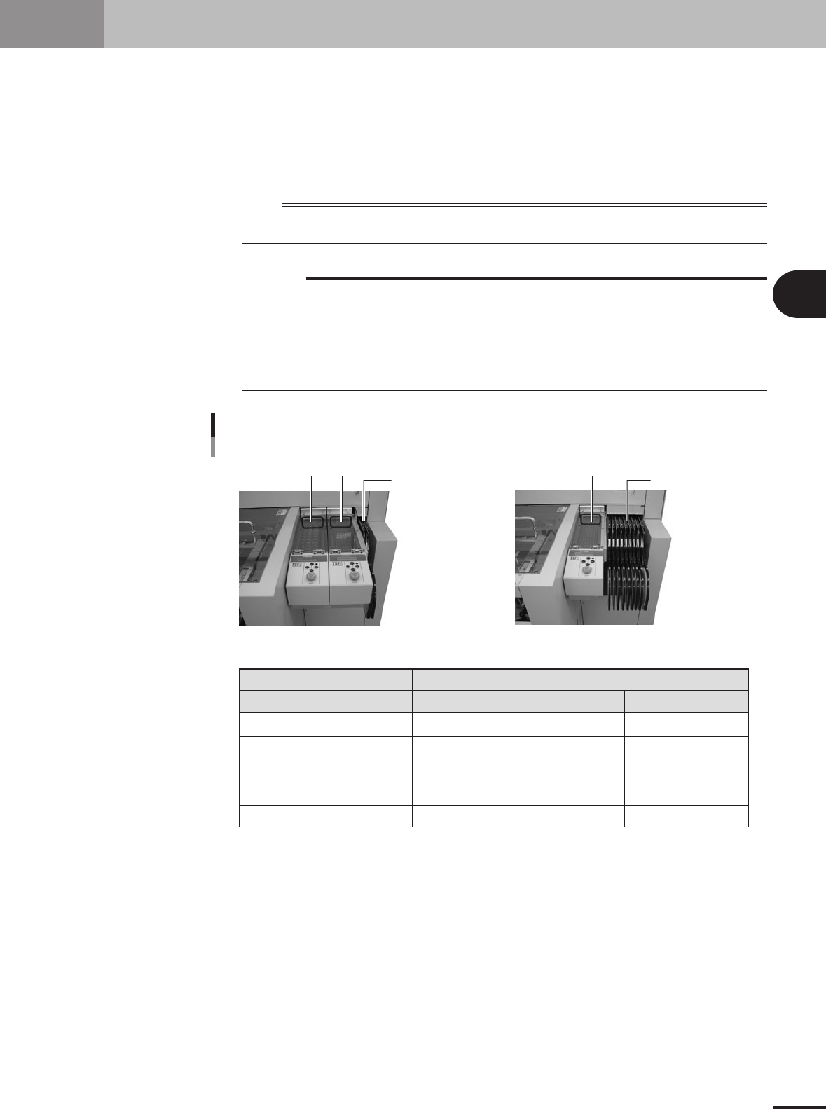
Changing the TSF1 setup
Position 1 Position 2
One TSF1 unit and nine 8mm feedersTwo TSF1 units and two 8mm feeders
8mm feeders x 2 8mm tape feeders x 9
Position 1
Position 1
Position 2
Feeder plate safety hoods of mounter
Tape guide plate
Shorting connector
Note 1: For safety reason, position 2 can not be used when only 1 TSF1 unit is installed.
1 unit
Specifications A
Cannot be installed (Note 1)
Uses Nos. 2 and 3.
Uses Nos. 2 and 3.
Use at position 2.
2 units
Specifications B
Specifications C
Uses No. 3
Uses No. 3
Not used
Not used
--
--
Uses Nos. 1, 2 and 3
Uses Nos. 1, 2 and 3
Uses at positions 1 and 2
Number of TSF1 units / Installation position
73300-5V-00
3 -2
3
Setup
3.1 Changing the TSF1 setups
w
WARNING
ALWAYS TURN OFF THE MOUNTER POWER SWITCH BEFORE CHANGING THE TSF1 SETUPS.
CHANGING THE SETUPS WHILE THE POWER IS TURNED ON MIGHT CAUSE AN ACCIDENT OR
FAULTY OPERATION.
3.1.1 Changing the setups: from specifications A to B
1
Remove the side safety cover 1.
Remove the three screws holding the side cover 1 and remove the side cover 1 from
the upper safety cover.
Set screw with washer (x 3)
Side safety cover 1
73301-5V-00
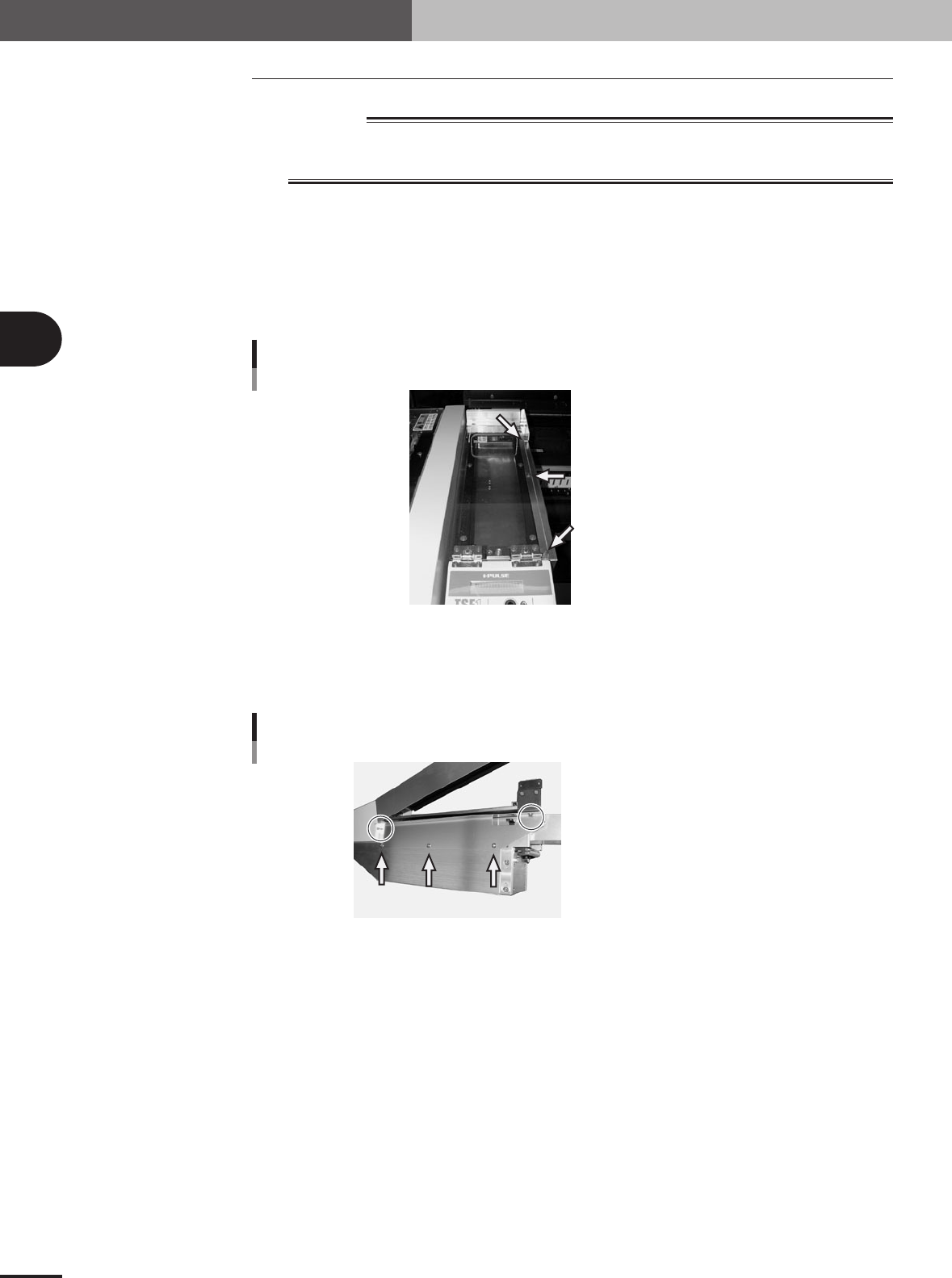
2
Remove the side safety cover 2.
Remove the five screws holding the side cover 2 and remove the side cover 2 from
the TSF1 main body.
Shown in circle: Set screw (x 2)
Pointed by arrow: Binding screw (x 3)
Side safety cover 2
73302-5V-00
3 -3
3
Setup
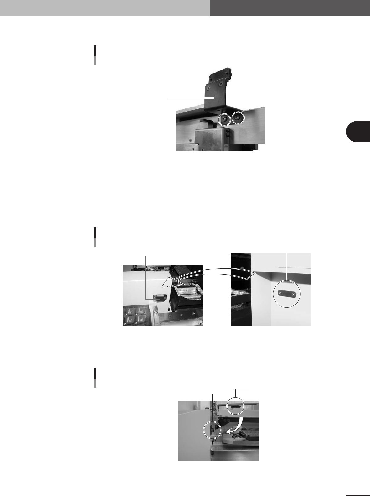
3
Detach the magnet catch assembly.
Remove the two screws and detach the magnet catch assembly.
Magnet catch 1
Magnet catch assembly
(standard position)
73303-5V-00
4
Install the TSF1 on the feeder plate.
While holding the TSF1 body carefully with the upper safety cover fully opened,
install it in position 1 on the feeder plate.
5
Attach the magnet catch assembly to the mounter.
Take the magnet catch assembly apart and then attach the magnet catch with the
screw catch plate and two screws (supplied) to the side of the conveyor cover of the
mounter.
Magnet catch 2
Magnet catch assembly
(conveyor cover position)
Screw catch plate
73304-5V-00
6
Check the open/close movement of the upper safety cover.
Open and close the upper safety cover a few times and check that the safety switch
push plate securely pushes the cover safety switch.
Cover safety switch
Cover safety switch
Safety switch push plate
73305-5V-00