M3plus_OperationManual_e.pdf - 第256页
3 - 3 3 Setup 3 Detach the magnet catch assembly. Remove the two screws and detach the magnet catch assembly. Magnet catch 1 Magnet catch assembly (standard position) 73303-5V-00 4 Install the TSF1 on the feeder plate. W…
3 -2
3
Setup
3.1 Changing the TSF1 setups
w
WARNING
ALWAYS TURN OFF THE MOUNTER POWER SWITCH BEFORE CHANGING THE TSF1 SETUPS.
CHANGING THE SETUPS WHILE THE POWER IS TURNED ON MIGHT CAUSE AN ACCIDENT OR
FAULTY OPERATION.
3.1.1 Changing the setups: from specifications A to B
1
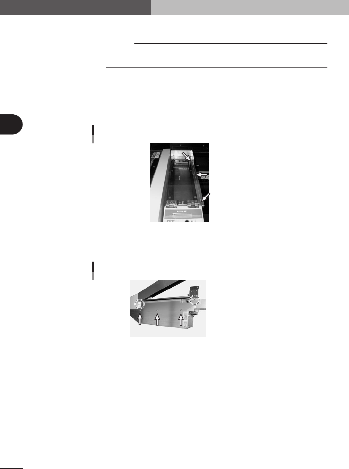
Remove the side safety cover 1.
Remove the three screws holding the side cover 1 and remove the side cover 1 from
the upper safety cover.
Set screw with washer (x 3)
Side safety cover 1
73301-5V-00
2
Remove the side safety cover 2.
Remove the five screws holding the side cover 2 and remove the side cover 2 from
the TSF1 main body.
Shown in circle: Set screw (x 2)
Pointed by arrow: Binding screw (x 3)
Side safety cover 2
73302-5V-00
3 -3
3
Setup
3
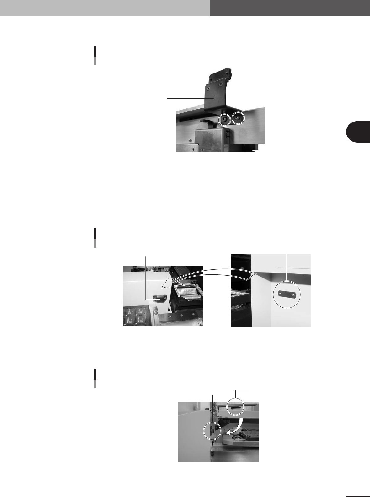
Detach the magnet catch assembly.
Remove the two screws and detach the magnet catch assembly.
Magnet catch 1
Magnet catch assembly
(standard position)
73303-5V-00
4
Install the TSF1 on the feeder plate.
While holding the TSF1 body carefully with the upper safety cover fully opened,
install it in position 1 on the feeder plate.
5
Attach the magnet catch assembly to the mounter.
Take the magnet catch assembly apart and then attach the magnet catch with the
screw catch plate and two screws (supplied) to the side of the conveyor cover of the
mounter.
Magnet catch 2
Magnet catch assembly
(conveyor cover position)
Screw catch plate
73304-5V-00
6
Check the open/close movement of the upper safety cover.
Open and close the upper safety cover a few times and check that the safety switch
push plate securely pushes the cover safety switch.
Cover safety switch
Cover safety switch
Safety switch push plate
73305-5V-00
3 -4
3
Setup
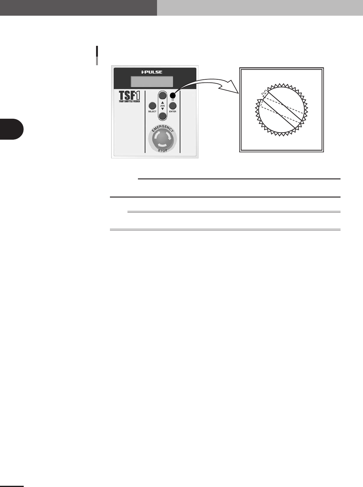
3.1.2 Changing the setups: from specifications A to C
Use a slotted screwdriver to change the ID setting from "ID 1" to "ID 2".
0
1
2
3
4
5
6
7
8
9
A
B
C
D
E
F
ID dial position (when set to ID 2)
Details of ID dial
73306-5V-00
c
CAUTION
Use the slotted screwdriver that fits the ID dial slot. (A 4-mm blade width would be the best.) If
you use a screwdriver that does not match the ID dial slot, the ID dial might be damaged.
n
NOTE
The ID information on the TSF1 is recognized by the mounter when it starts up. When you have changed the ID
number, check it on the LCD display of the TSF1 after the mounter has started.