M3plus_OperationManual_e.pdf - 第31页
1 P art names and functions 1- 10 6. Axis configuration The machine axis configuration and operation are shown in the drawing and table below. MMM Head X axis Y axis W axis Z1 to Z4 axis R axis Plus Minus F ront of the m…

1
Part names and functions
1 -9
5. Conveyor unit
The conveyor unit used to clamp a PCB in mounting position consists of the following parts.
PCB
2
3
1
4
Conveyor units
23130-5E-20
1 Main stopper
When a PCB is carried in on the conveyor, the main stopper halts travel of the PCB in the component
mounting position.
2 Push-up plate
The push-up plate moves up and down by the air cylinder to support the PCB from the bottom, with
push-up pins attached on the plate.
3 Push-up pins
These pins are arranged on the push-up plate and secure the PCB by pushing it up from the bottom.
4 PCB clamp (PCB clamp unit)
This unit moves up with the push-up plate to clamp the PCB by pushing its edges up.
1
Part names and functions
1-10
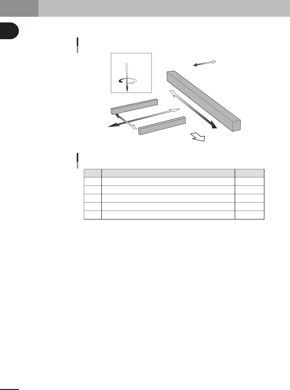
6. Axis configuration
The machine axis configuration and operation are shown in the drawing and table below.
MMM Head
X axis
Y axis
W axis
Z1 to Z4 axis
R axis
Plus
Minus
Front of the machine
Axis configuration and plus/minus directions
23119-5E-20
X
Y
Z1 to Z4
R
W
Axis Function
Function of each axis
Moves the conveyor (W-axis) in the X-axis direction.
Moves the head in the direction perpendicular to the PCB transfer direction on the conveyor.
Controls the height of the head assembly each head.
Rotates the nozzle shafts of the head assembly.
Adjusts the conveyor width.
Remarks
25108-5E-20

Table of Contents
1. Before operation . . . . . . . . . . . . . . . . . . . . . . . . . . . . . . . . 2-1
1.1 Canceling emergency stop . . . . . . . . . . . . . . . . . . . . . . . . . . . . . . 2-1
1.2 Clearing an error . . . . . . . . . . . . . . . . . . . . . . . . . . . . . . . . . . . . . 2-2
2. Operation monitor and buttons . . . . . . . . . . . . . . . . . . . . 2-3
2.1 Basic configuration of operation screen . . . . . . . . . . . . . . . . . . . 2-3
2.2 Various buttons and parameter input boxes . . . . . . . . . . . . . . . . 2-4
3. Starting and stopping the machine. . . . . . . . . . . . . . . . . 2-7
3.1 Inspection before operation . . . . . . . . . . . . . . . . . . . . . . . . . . . . . 2-8
3.2 Starting the machine . . . . . . . . . . . . . . . . . . . . . . . . . . . . . . . . . . 2-9
3.3 Starting and warming up the machine . . . . . . . . . . . . . . . . . . . . 2-11
3.4 Changing the conveyor unit setup . . . . . . . . . . . . . . . . . . . . . . . 2-13
3.4.1 Conveyor width . . . . . . . . . . . . . . . . . . . . . . . . . . . . . . . . . . . . . . 2-14
3.4.2 Push-up pins . . . . . . . . . . . . . . . . . . . . . . . . . . . . . . . . . . . . . . . . 2-15
4. Starting and finishing production . . . . . . . . . . . . . . . . . 2-16
4.1 Starting production . . . . . . . . . . . . . . . . . . . . . . . . . . . . . . . . . . 2-16
4.2 Finishing PCB production . . . . . . . . . . . . . . . . . . . . . . . . . . . . . 2-28
Chapter 2 Basic operation