M3plus_OperationManual_e.pdf - 第35页
2 - 2 2 Basic oper ation 1.2 Clearing an error If an error occurs a buzzer sounds and a yellow warning screen appears. To clear the error, use the following steps. 1 Turn off the buzzer. Press the [ERROR CLEAR] button on…
2
Basic operation
2 -1
1. Before operation
The following explains how to cancel emergency stop and clear errors. Read before operating the
machine.
1.1 Canceling emergency stop
Follow these steps to cancel emergency stop.
1
Release the emergency stop button.
Turn the emergency stop button clockwise to release it.
2
Check safety.
Before continuing the procedure, check the surrounding area for safety.
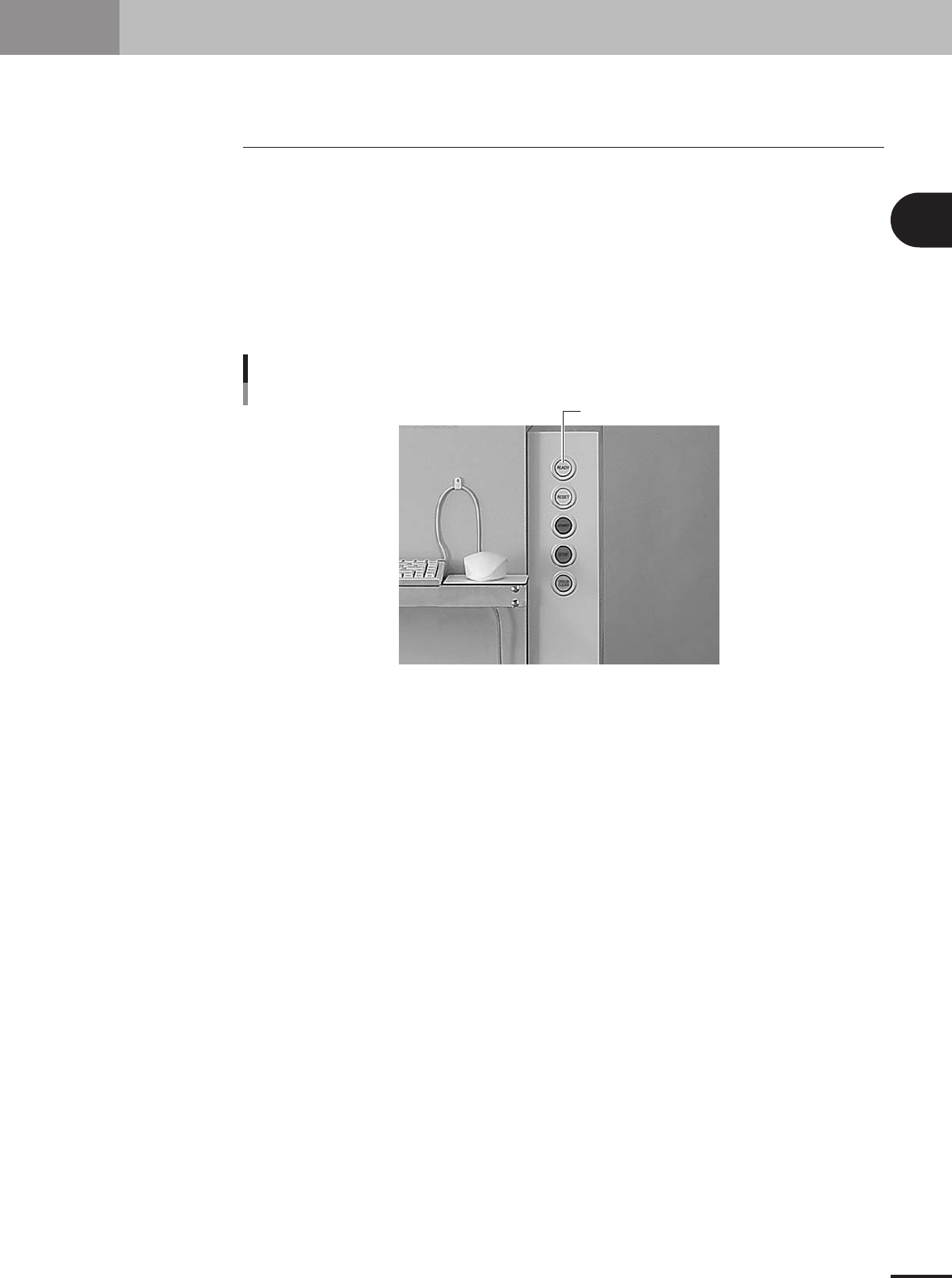
3
Press the [READY] button.
Pressing the [READY] button on the operation panel turns on the servomotors.
Press the [READY] button to turn on the servo.
[READY] button
23103-5E-2A
4
Check the signal light and screen display.
Check that the red lamp of the signal light is off and the emergency stop sign on the
operation screen is now off.

2 -2
2
Basic operation
1.2 Clearing an error
If an error occurs a buzzer sounds and a yellow warning screen appears. To clear the
error, use the following steps.
1
Turn off the buzzer.
Press the [ERROR CLEAR] button on the operation panel or the [BUZZER OFF] button
on the error screen to turn off the buzzer.
2
Check the cause of the error.
Possible causes are displayed on the lower part in the error screen, so check or make
a note of the description.
3
Clear the error screen.
Press the [ERROR CLEAR] button on the operation panel again or the [ERROR CLEAR]
button on the error screen to clear the error screen.
4
Check the signal light and screen display.
Check that the yellow lamp of the signal light is off and the error message on the
upper left of the status area on the operation screen is now off.
1. Before operation
2
Basic operation
2 -3
2. Operation monitor and buttons
The basic configuration and operation methods of the software screens are explained in this section.
Please read through this section before operating the machine.
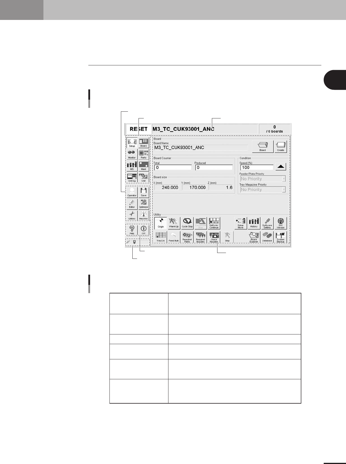
2.1 Basic configuration of operation screen
The operation screen can be divided into the "Status area", "Main menu button area" and
"Submenu button and parameter area" as shown below.
Main menu button area 1
Main menu button area 3
Main menu button area 2
Status area
Submenu button and
parameter area
Indicator area
Operation screen basic elements
Setup screen
27201-5E-20
Status area
Main menu button area 1
Main menu button area 2
Main menu button area 3
Submenu button and
parameter area
Indicator area
Displays the current machine status on the left end, the selected
PCB name in the middle and the number of PCBs that have been produced
on the right end.
Shows the main menu buttons used to operate the machine.
The submenu button and parameter area will change according to the selected
main menu button.
Shows the menu buttons used to call up auxiliary functions of the machine.
Shows the [Help] button to call up the help screen and also the [Off] button
to quit the software.
Displays the submenu buttons and parameters for machine operation and
data setting.
This area will change according to the selected main menu button.
[MSP] icon: Appears in color when the MSP (option) is connected to the
machine.
[Communication] icon: Appears in color when the machine is connected to
an external unit through the RS-232C.
Area on screen
25201-5E-20