M3plus_OperationManual_e.pdf - 第51页
2 - 18 2 Basic oper ation 4. Starting and finishing production 3 Check the other setup items. Return to the [Setup] screen, and press the following buttons to check or change the setting data. [Setup] screen 4321 5 6 272…
2 -17
2
Basic operation
4. Starting and finishing production
2
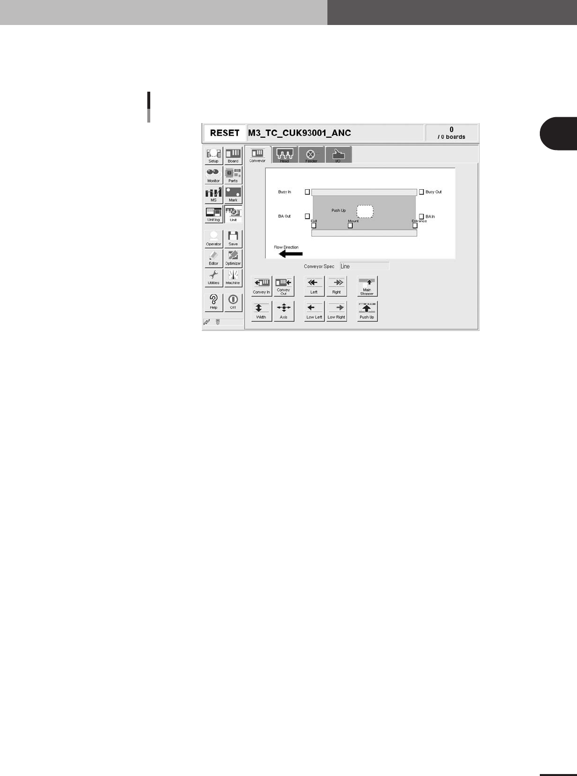
Set up the conveyor unit.
Open the [Unit] - [Conveyor] tab screen, and adjust the conveyor width and conveyor
units according to the PCB. Refer to "3.4. Changing the conveyor unit setup" for
details.
[Unit] - [Conveyor] screen
27304-5E-20
2 -18
2
Basic operation
4. Starting and finishing production
3
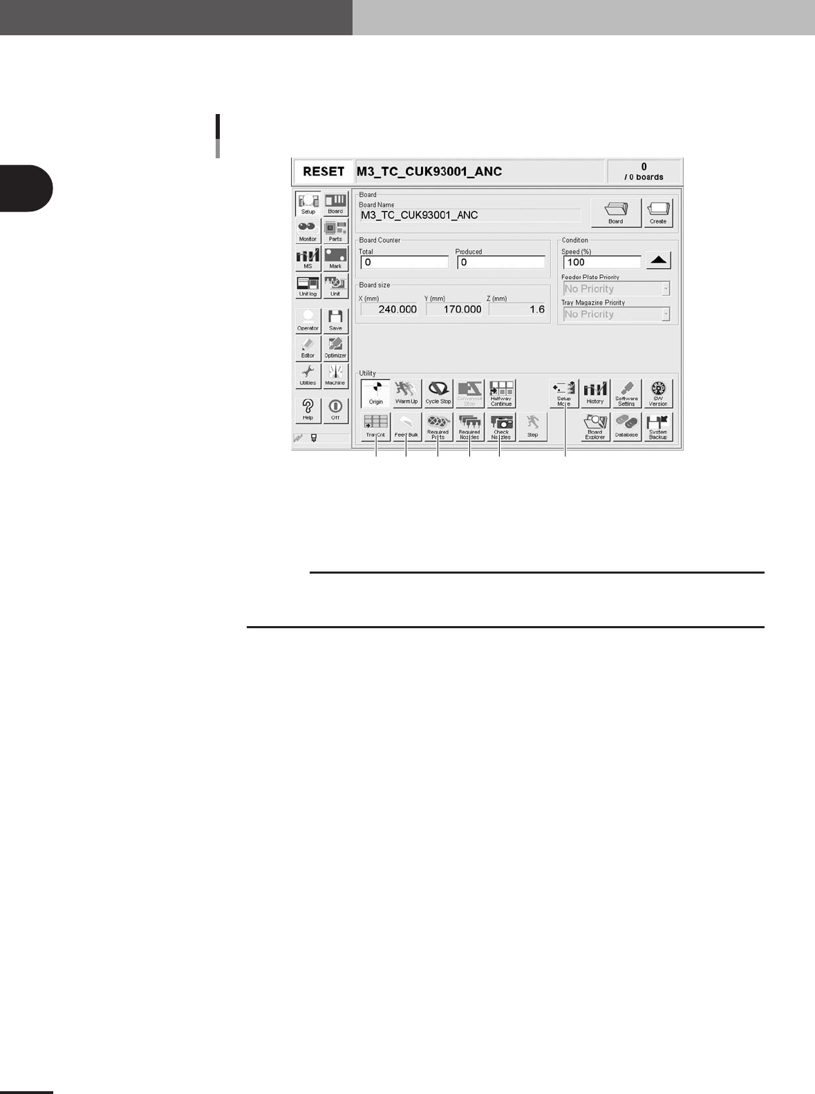
Check the other setup items.
Return to the [Setup] screen, and press the following buttons to check or change the
setting data.
[Setup] screen
4321
56
27201-5E-2C
1 [Check Nozzles]
Checks the nozzle tip condition with the vision camera. If an error occurs with this check, clean the
nozzle.
c
CAUTION
When the [Check Nozzles] button is pressed, the head assembly will immediately move to the
camera position. Since nozzles gradually gather dust with operation time, repeating nozzle
checks may result in OK and NG randomly. But this is not a malfunction.
2 [Required Nozzles]
Displays the nozzle type that can be attached to each head. When your machine has no nozzle station
or uses a head not designed for auto nozzle change, check that the correct nozzle is attached to each
head by referring to the displayed message.
3 [Required Parts]
Displays the designated feeder set positions and components to be mounted. Check whether the
necessary feeders are installed in the correct feeder set positions on the feeder plate.
4 [Feed Bulk]
Press this button to feed bulk components to the top of the bulk feeder guide.
5 [Setup Move]
Moves the X-axis conveyor and head assembly to the positions that allow you to make the feeder and
conveyor setups easily.
6 [TrayCnt]
This is enabled only when a tray feeder is used. Pressing this button opens the Tray Counter window
that displays the number of X and Y components used from a tray that is supposed to be in a matrix
format. To clear the display, press the [Cleat 1 Part] or [Clear All Parts] button.
2 -19
2
Basic operation
4. Starting and finishing production
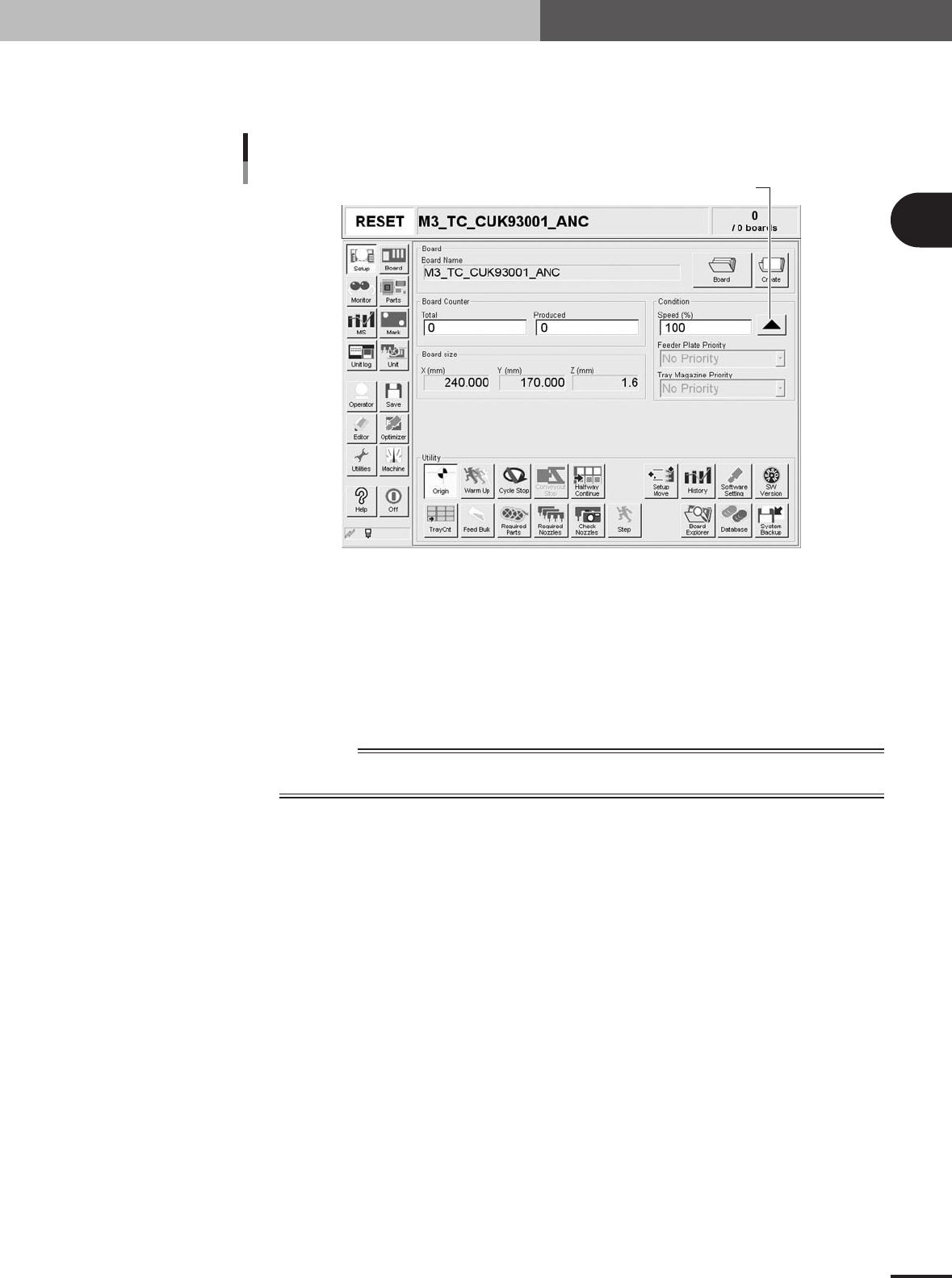
4
Set the operation speed.
The currently set operation speed is displayed in the "Speed" box. Press the UP arrow
button to change the operation speed.
Set the operation speed.
Setting the operation speed
27201-5E-2D
5
Start operation.
1.Release the emergency stop button, and press the [READY] button on the operation
panel.
2.Check that the surroundings are safe, and then press the [START] button on the
operation panel.
3.When the entrance sensor detects the PCB, the conveyor belt will start rotation. The
PCB will be transferred to the work position, and component mounting will start.
w
WARNING
NEVER ENTER THE HEAD ASSEMBLY MOVEMENT RANGE WHILE THE GREEN SIGNAL LAMP
IS ON (DURING AUTOMATIC OPERATION).