M3plus_OperationManual_e.pdf - 第52页
2 - 19 2 Basic oper ation 4. Starting and finishing production 4 Set the operation speed. The currently set operation speed is displayed in the "Speed" box. Press the UP arrow button to change the operation spe…
2 -18
2
Basic operation
4. Starting and finishing production
3
Check the other setup items.
Return to the [Setup] screen, and press the following buttons to check or change the
setting data.
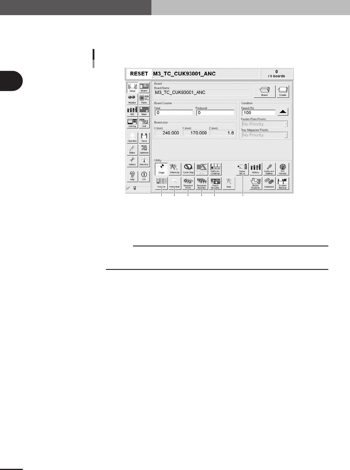
[Setup] screen
4321
56
27201-5E-2C
1 [Check Nozzles]
Checks the nozzle tip condition with the vision camera. If an error occurs with this check, clean the
nozzle.
c
CAUTION
When the [Check Nozzles] button is pressed, the head assembly will immediately move to the
camera position. Since nozzles gradually gather dust with operation time, repeating nozzle
checks may result in OK and NG randomly. But this is not a malfunction.
2 [Required Nozzles]
Displays the nozzle type that can be attached to each head. When your machine has no nozzle station
or uses a head not designed for auto nozzle change, check that the correct nozzle is attached to each
head by referring to the displayed message.
3 [Required Parts]
Displays the designated feeder set positions and components to be mounted. Check whether the
necessary feeders are installed in the correct feeder set positions on the feeder plate.
4 [Feed Bulk]
Press this button to feed bulk components to the top of the bulk feeder guide.
5 [Setup Move]
Moves the X-axis conveyor and head assembly to the positions that allow you to make the feeder and
conveyor setups easily.
6 [TrayCnt]
This is enabled only when a tray feeder is used. Pressing this button opens the Tray Counter window
that displays the number of X and Y components used from a tray that is supposed to be in a matrix
format. To clear the display, press the [Cleat 1 Part] or [Clear All Parts] button.
2 -19
2
Basic operation
4. Starting and finishing production
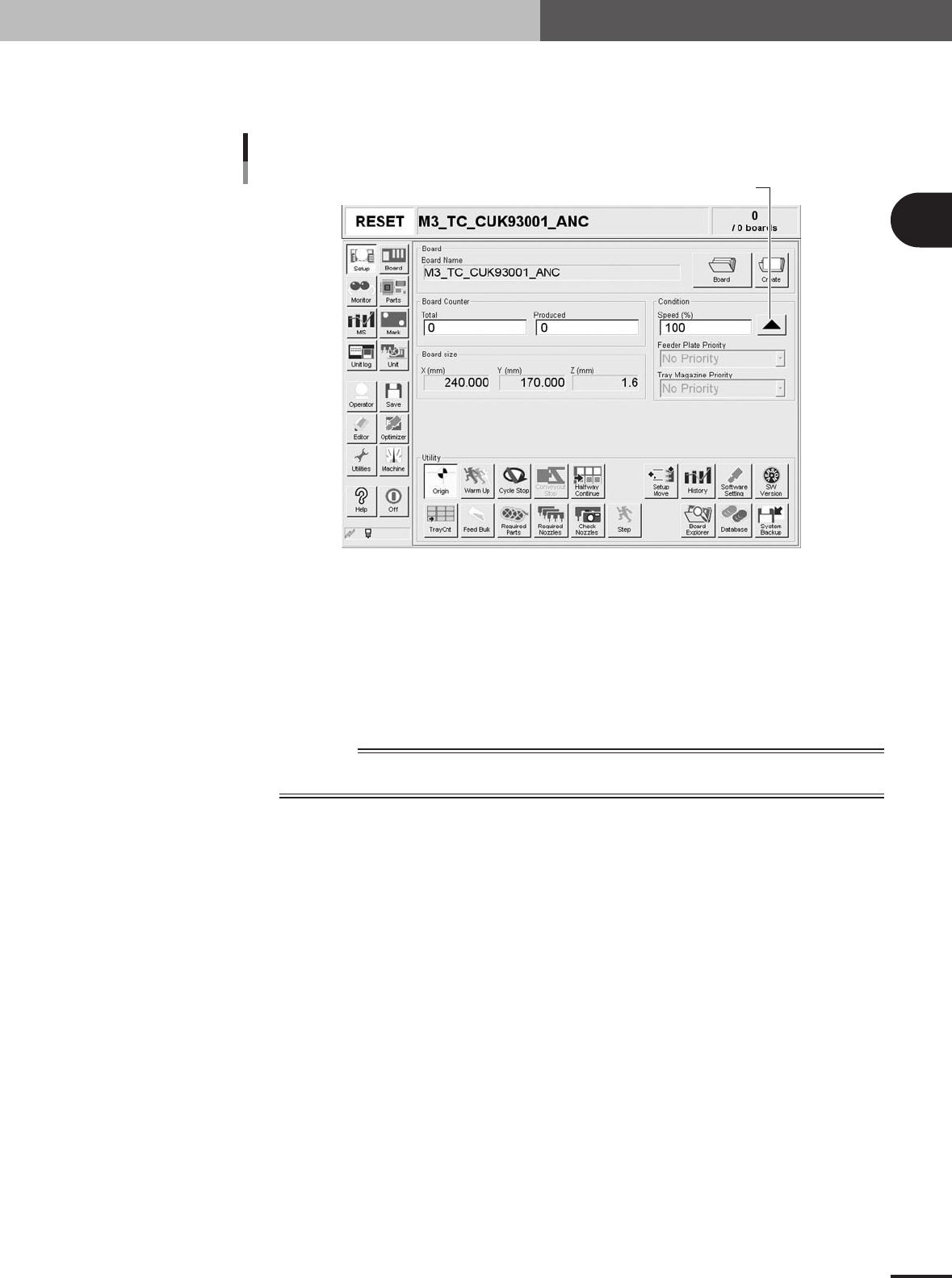
4
Set the operation speed.
The currently set operation speed is displayed in the "Speed" box. Press the UP arrow
button to change the operation speed.
Set the operation speed.
Setting the operation speed
27201-5E-2D
5
Start operation.
1.Release the emergency stop button, and press the [READY] button on the operation
panel.
2.Check that the surroundings are safe, and then press the [START] button on the
operation panel.
3.When the entrance sensor detects the PCB, the conveyor belt will start rotation. The
PCB will be transferred to the work position, and component mounting will start.
w
WARNING
NEVER ENTER THE HEAD ASSEMBLY MOVEMENT RANGE WHILE THE GREEN SIGNAL LAMP
IS ON (DURING AUTOMATIC OPERATION).
2 -20
2
Basic operation
4. Starting and finishing production
6
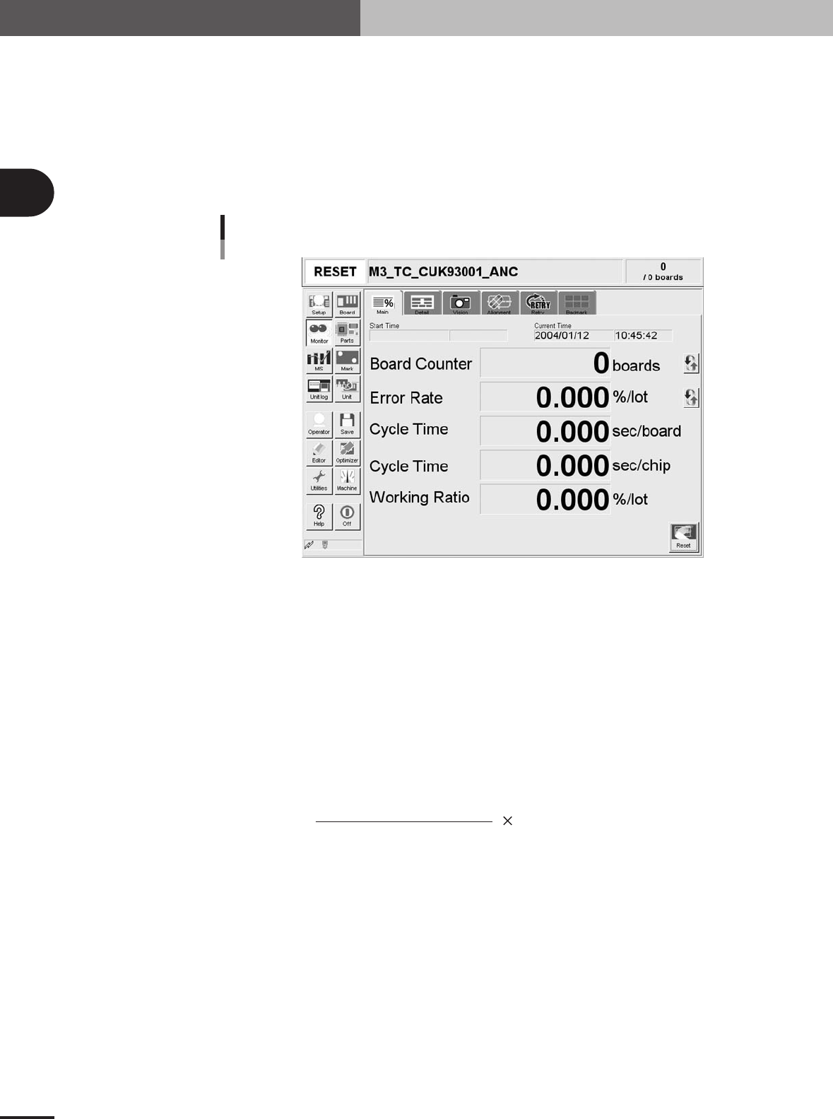
Display the operation monitor as required.
Press the [Monitor] button to confirm the operation status during production.
The mounting information can be confirmed by selecting the [Main], [Detail], [Vision],
[Alignment] and [Retry] tabs.
Monitor: Main
The [Monitor]-[Main] tab screen shows you the real-time production status such as the PCB count
and cycle time. Displaying this screen during production is handy. All information will be cleared
when the PCB type is changed.
Monitor: Main
27305-5E-20
Start Time
Displays the date and time that the PCB data currently being produced was changed.
Current Time
Shows the current date and time (system clock time in the machine).
Board Counter
Displays the number of PCBs produced after changing to the current PCB data. The PCB data reset
midway is not counted unless mounted midway.
Error Rate
Displays the rate of discarded components due to pickup or recognition errors with respect to all
components that have been consumed after changing to the current production PCB data. This data is
updated when the production of one PCB is completed.
Number of discarded components
To tal component consumption
Error rate (%) = 100
Cycle Time (sec/board)
Shows the average (second/board) of the mounting time per board. The data is updated when
mounting is completed. The cycle time includes the mark (including fiducial and bad marks)
recognition time, the component pickup time, component recognition time, mounting time, retry
operation time, component dump time and nozzle change time.
The transfer time and stop time (time stopped with error or [STOP] button) is not included.
Cycle Time (sec/chip)
Shows the time (second) to mount one component on the PCB. This is the time obtained by dividing
the time for one sequence from pickup to mounting by the number of components mounted in that
sequence.