M3plus_OperationManual_e.pdf - 第53页
2 - 20 2 Basic oper ation 4. Starting and finishing production 6 Display the operation monitor as required. Press the [Monitor] button to confirm the operation status during production. The mounting information can be co…
2 -19
2
Basic operation
4. Starting and finishing production
4
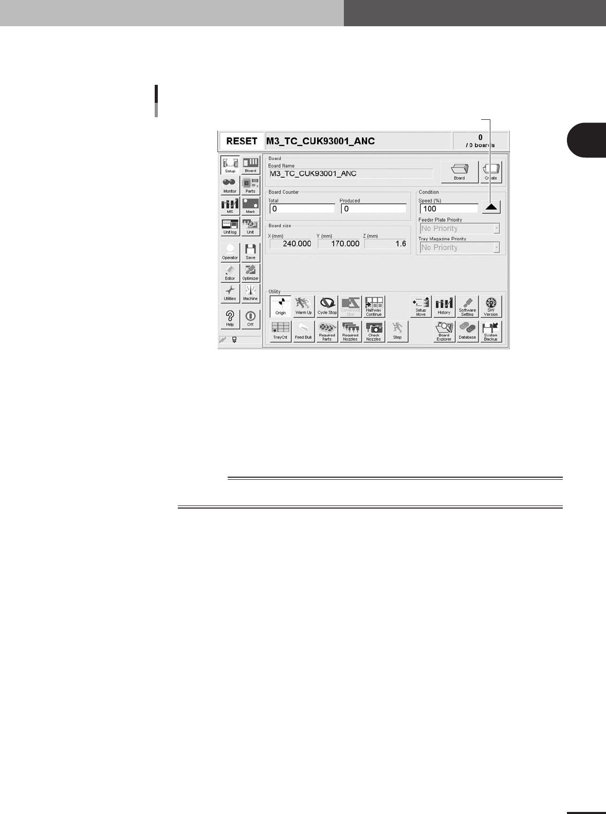
Set the operation speed.
The currently set operation speed is displayed in the "Speed" box. Press the UP arrow
button to change the operation speed.
Set the operation speed.
Setting the operation speed
27201-5E-2D
5
Start operation.
1.Release the emergency stop button, and press the [READY] button on the operation
panel.
2.Check that the surroundings are safe, and then press the [START] button on the
operation panel.
3.When the entrance sensor detects the PCB, the conveyor belt will start rotation. The
PCB will be transferred to the work position, and component mounting will start.
w
WARNING
NEVER ENTER THE HEAD ASSEMBLY MOVEMENT RANGE WHILE THE GREEN SIGNAL LAMP
IS ON (DURING AUTOMATIC OPERATION).
2 -20
2
Basic operation
4. Starting and finishing production
6
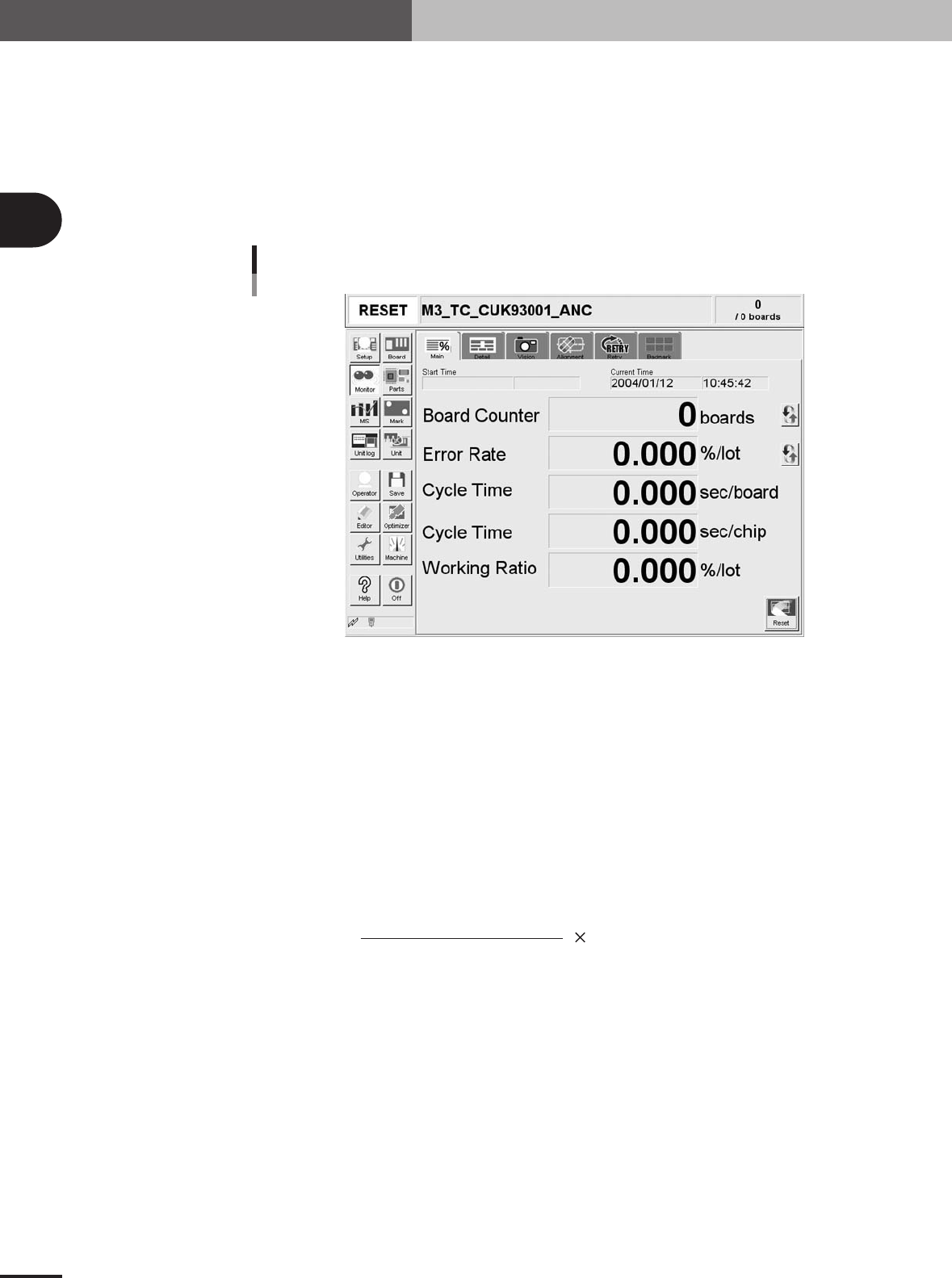
Display the operation monitor as required.
Press the [Monitor] button to confirm the operation status during production.
The mounting information can be confirmed by selecting the [Main], [Detail], [Vision],
[Alignment] and [Retry] tabs.
Monitor: Main
The [Monitor]-[Main] tab screen shows you the real-time production status such as the PCB count
and cycle time. Displaying this screen during production is handy. All information will be cleared
when the PCB type is changed.
Monitor: Main
27305-5E-20
Start Time
Displays the date and time that the PCB data currently being produced was changed.
Current Time
Shows the current date and time (system clock time in the machine).
Board Counter
Displays the number of PCBs produced after changing to the current PCB data. The PCB data reset
midway is not counted unless mounted midway.
Error Rate
Displays the rate of discarded components due to pickup or recognition errors with respect to all
components that have been consumed after changing to the current production PCB data. This data is
updated when the production of one PCB is completed.
Number of discarded components
To tal component consumption
Error rate (%) = 100
Cycle Time (sec/board)
Shows the average (second/board) of the mounting time per board. The data is updated when
mounting is completed. The cycle time includes the mark (including fiducial and bad marks)
recognition time, the component pickup time, component recognition time, mounting time, retry
operation time, component dump time and nozzle change time.
The transfer time and stop time (time stopped with error or [STOP] button) is not included.
Cycle Time (sec/chip)
Shows the time (second) to mount one component on the PCB. This is the time obtained by dividing
the time for one sequence from pickup to mounting by the number of components mounted in that
sequence.

2 -21
2
Basic operation
4. Starting and finishing production
Working Ratio
This is the machine unit's working ratio. This ratio is not affected by the status of the upstream and
downstream machines, and is calculated with the following expression. Generally, the mounter
working ratio is 40 to 70%.
Cumulative mounting time + cumulative transfer time
[
(Production completion time - setup completion time)
- cumulative standby time
]
× 100
Working ratio (%)
=
Cumulative mounting time : Total time that head is operating
Cumulative transfer time : Total transfer time (loading/unloading)
Cumulative standby time : Total time upstream or down stream machine stands by
Production completion time : Time changed to next production PCB
Setup completion time : Time [START] button was pressed and operation started
[Reset]
Resets the production control information, including each data and current production quantity,
current unloader quantity, scheduled production quantity and scheduled unloader quantity. The
"Board Counter" value on the [Setup] screen is also reset when this production data is reset.