M3plus_OperationManual_e.pdf - 第66页
3 Creating the PCB data 3 - 1 1. Over view The PCB data is indexed by each individual PCB name. Each PCB type consists of various information and parameters as shown below, which can be selected or checked with the menu …

4.10 Using component feeders other than tape feeders . . . . . . . . . . 3-49
4.10.1 Setting the stick feeder component data . . . . . . . . . . . . . . . . . . . 3-49
4.10.2 Tray shuttle feeder . . . . . . . . . . . . . . . . . . . . . . . . . . . . . . . . . . . . 3-53
5. Creating the mark information . . . . . . . . . . . . . . . . . . . 3-59
5.1 Creating procedure . . . . . . . . . . . . . . . . . . . . . . . . . . . . . . . . . . 3-60
5.2 Basic parameters . . . . . . . . . . . . . . . . . . . . . . . . . . . . . . . . . . . . 3-61
5.3 Shape parameters . . . . . . . . . . . . . . . . . . . . . . . . . . . . . . . . . . . . 3-62
5.4 Vision parameters . . . . . . . . . . . . . . . . . . . . . . . . . . . . . . . . . . . 3-64
5.5 Mark Adjust mode . . . . . . . . . . . . . . . . . . . . . . . . . . . . . . . . . . . 3-66
3
Creating the PCB data
3 -1
1. Overview
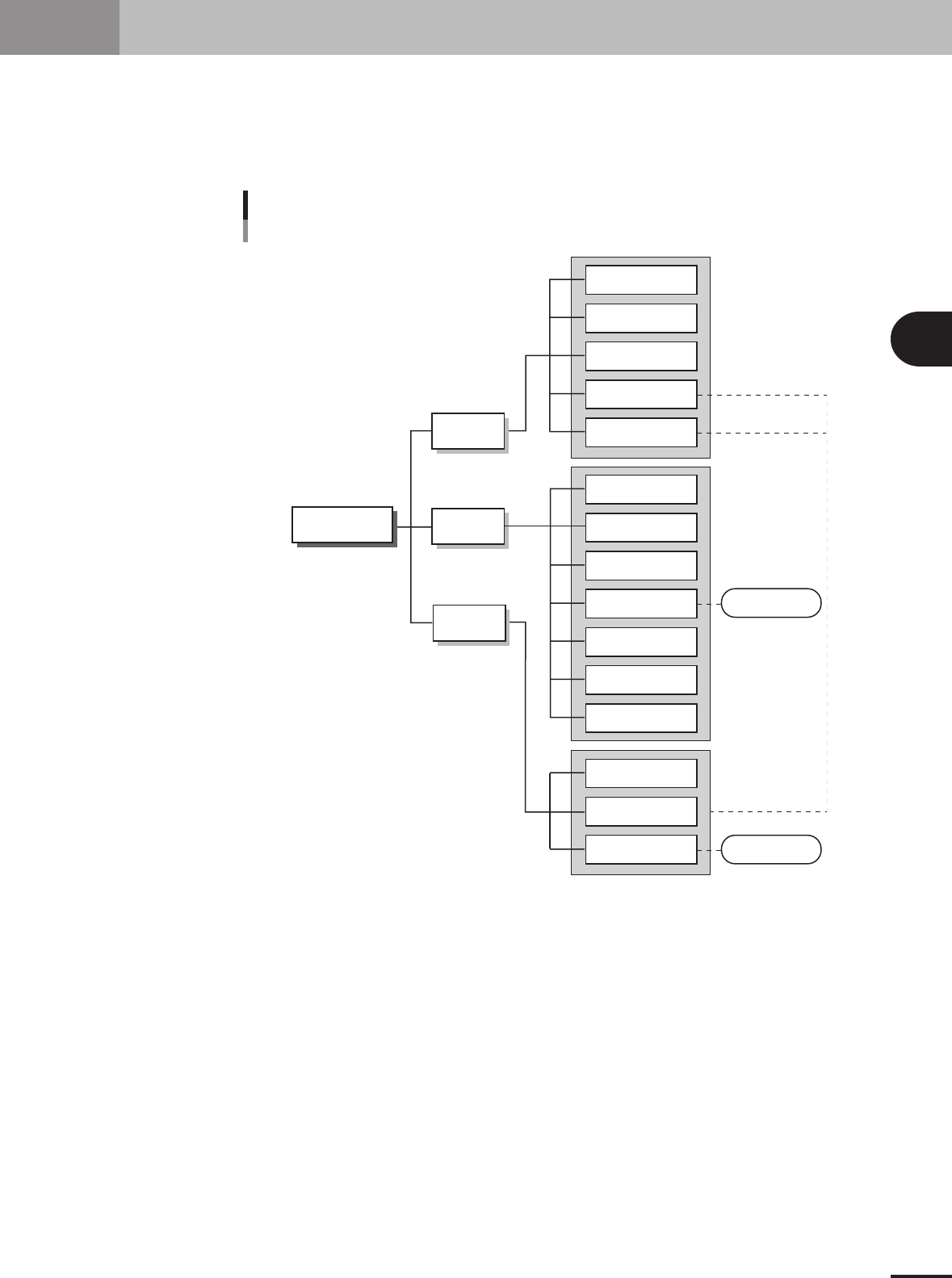
The PCB data is indexed by each individual PCB name. Each PCB type consists of various information
and parameters as shown below, which can be selected or checked with the menu button and tab on
the operation screen. This section describes basic methods for creating PCB data so that you will
understand what data is needed for what item. After you have obtained a complete understanding of
these methods, begin actual work according to the desired method.
PCB name
Parts
Pick
Basic
Parts Adjust mode
Vision
Mount
Tray
Option
Shape
Shape
Vision
Basic
Mount
Board
Various parameters
Fiducial
Badmark
Offset
Board
PCB data structure
Mark
Mark Adjust mode
23401-5E-20
3
Creating the PCB data
3-2
2. Registering and selecting the PCB name
2.1 Registering PCB names
To create new PCB data for production, you must first register the PCB name. There are
some methods for registering a PCB name.
1. Registering a new PCB name
If no basic data is found in the previously registered PCB data. You should register a new PCB
name with empty data and then enter necessary data.
2. Utilizing PCB data already registered
Make a copy of PCB data which is already registered in the machine.
3. Converting CAD data or other manufacturer's mounter data
After converting CAD data or other manufacturer's mounter data into a standard format, take its
component coordinate data into the machine to create data that can be used with i-PULSE full
vision series mounters.
The following steps explain the procedure in "1. Registering a new PCB
name".
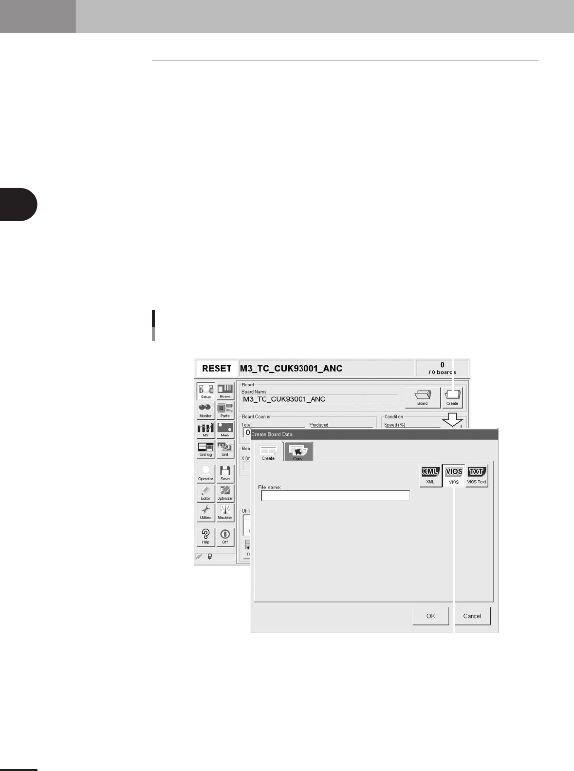
1
Press the [Create] button on the Setup screen.
The "Create Board Data" dialog box appears as shown below.
[Create] button
Select the format to save data.
[Create] button
27401-5E-20