M3plus_OperationManual_e.pdf - 第73页
3 - 8 3 Creating the PCB data 3. Creating the PCB information Q: Precede Pick Set to "NotUse" in most cases. When set to "Use", the head assembly starts moving to pick up and recognize components as s…

3 -7
3
Creating the PCB data
3. Creating the PCB information
I: Unloader Count Max.
Specify the number of PCBs that can be stored in one rack of the unloader. When the specified
number of PCBs has been produced and transferred out into the unloader, the machine stops
transfer of the production PCB until the unloader replaces the rack. If this is set to "0", the machine
continues production without checking the number of PCBs transferred out into the unloader. Enter
"0" in the following cases.
• The unloader being used provides a rack switching signal output.
• This setting data is to be used for the machine just before reflowing.
J: Board Fix Device
Select the proper PCB clamping method according to the PCB to be produced.
"Edge Clamp" :
PCB is clamped on the conveyor with the edge clamps, push-in unit and push-up pins, without
using the locate pins.
"Locate Pin" (option) :
PCB is clamped on the conveyor only with the locate pins.
"Pin+PushUP" (option) :
PCB is clamped on the conveyor with the locate pins and push-up pins. This is the most accurate
and recommended method.
K: Pre Fix Timer sec
The machine begins to clamp the PCB immediately after it passes above the PCB sensor installed
just before the main stopper. The optimum clamping timing (delay time with respect to the sensor
detection) depends on the PCB size and conveyor speed. Use this parameter to set the clamp timing
(0.0 to 1.9 sec.).
L: Trans Height
After components are mounted, the machine permits the conveyor to carry out the PCB when the
push-up unit is lowered. If components have already been mounted on the reverse side of the PCB,
the push-up unit must be lowered sufficiently to avoid interference from push-up pins with those
components. This parameter specifies the height of the push-up unit at which the conveyor is
allowed to carry out each type of PCB. Enter the distance in millimeters from the point where the
push-up unit is raised to clamp the PCB. This distance can be 3 to 30mm.
M: Conveyor Timer sec
Set to "0.0" sec. for normal shape PCBs. If specially configured PCBs (for example, PCBs with
cutout parts or through-holes) are used and the exit sensor cannot detect them reliably, try setting
this timer in the range of 0.0 to 9.9 sec. The conveyor motor continues turning for the specified
time even after the PCB sensor turns off.
N: Alignment
Set to "UseAlign" to check the image of a component by vision recognition during component
pickup.
O: Vacuum Check
Set to "Check" to check whether a component is being picked up, by detecting the vacuum level, as
well as checking with the vision system.
P: Retry Sequence
The retry sequence when a pickup or recognition error occurs can be selected from the following
methods.
"Group":
Retry is repeated with the head which caused an error, until component mounting specified as one
group is complete.
"Block":
Retry is performed with the head which caused an error after component mounting in one block is
complete.
"Auto":
Retry is performed with any free head after component mounting in one block is complete.

3 -8
3
Creating the PCB data
3. Creating the PCB information
Q: Precede Pick
Set to "NotUse" in most cases. When set to "Use", the head assembly starts moving to pick up and
recognize components as soon as the preceding PCB has been carried out and the next PCB is
carried in. This will shorten the cycle time.
V: Conveyor X Speed
This parameter specifies the conveyor X-axis speed. If components move or slide just after
mounted on the PCB due to the X-axis movement, set this parameter to a lower speed.
X: Conveyor Motor Speed (%)
Set the conveyor motor speed (PCB transfer speed). With respect to the machine setting speed, the
conveyor speed can be adjusted to 50% on the plus side and 90% on the minus side in 10% steps.
3 -9
3
Creating the PCB data
3. Creating the PCB information
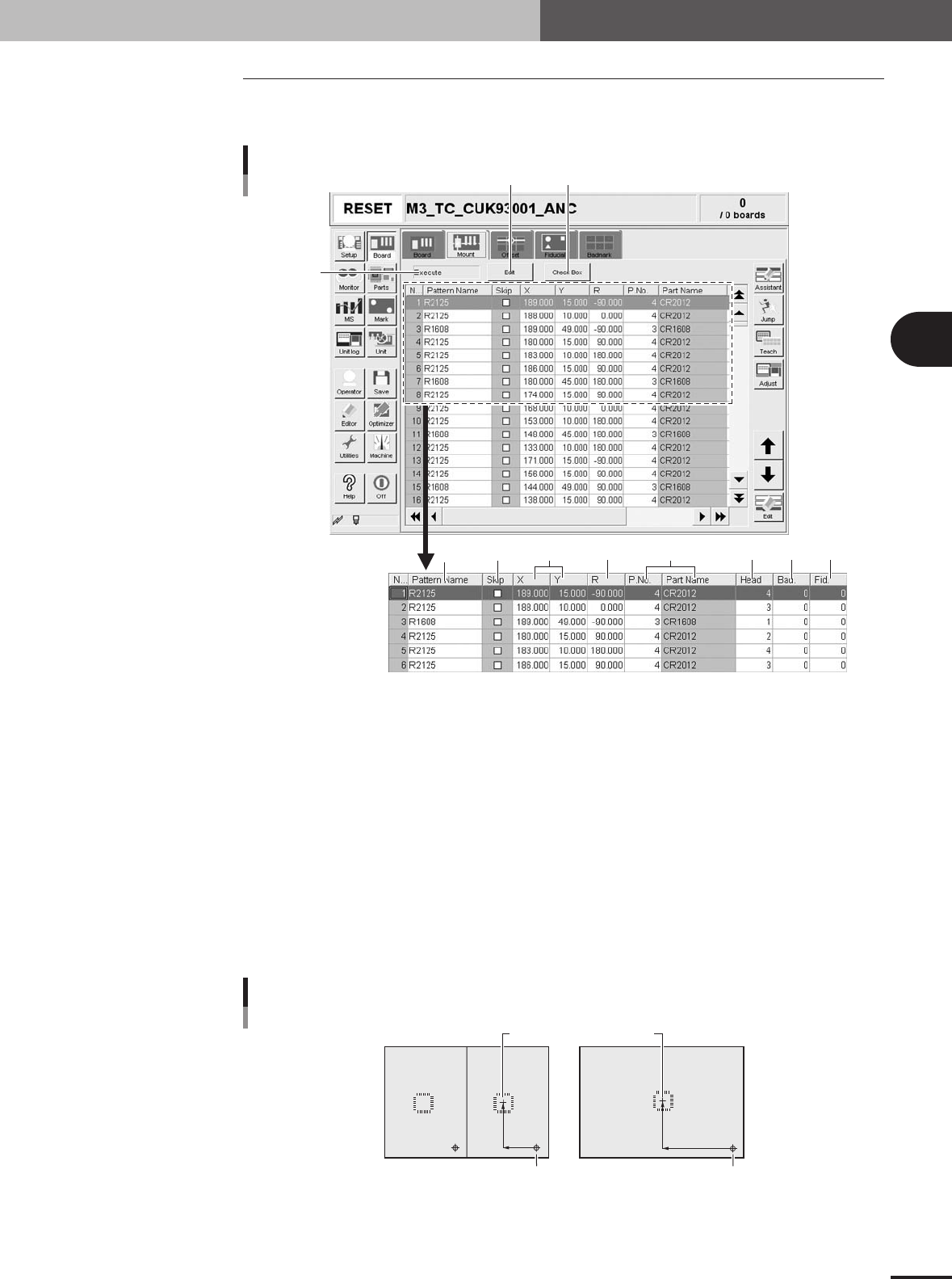
3.2 Mount parameters
Selecting the [Mount] tab opens the screen for specifying the mount parameters such as
mounting position data and component numbers to be mounted.
1
3
245 7 8 96
Mount parameter screen
10 11
27407-5E-20
1 Execute/Skip
Select "Exec." to mount components with this mount data, or select "Skip" to perform "pass opera-
tion" without picking up and mounting components (head moves as if to pick up and mount compo-
nents).
2 Pattern Name
Enter the land pattern name or symbol (ex., R23, U12, etc.) printed on the PCB.
3 Skip
Place a checkmark when not mounting a component at this mount point.
4 X, Y
For single PCBs, enter the XY coordinate data of the center of the mounting position relative to the
PCB origin. For multi-block PCBs, enter the position data relative to the reference block. You can
also use the teaching function to enter the XY coordinate data as explained below.
Mounting position relative to PCB origin
Center of mounting position
Block 2
PCB origin
Block repeat No.1
Block 1
23404-5E-20