M3plus_OperationManual_e.pdf - 第86页
3 - 21 3 Creating the PCB data 3. Creating the PCB information 3. 4-point fiducial function The "4-point fiducial" function is used to enhance the mounting position accuracy by recognizing 4 fiducial marks prov…
3 -20
3
Creating the PCB data
3. Creating the PCB information
3.4.3 Local fiducial functions
There are three kinds of local fiducial functions relating to mount data: "point fiducial",
"local fiducial" and "4-point fiducial" functions. These are generally called the local
fiducial functions.
The local fiducial functions are used to enhance the local mounting position accuracy of
individual mount data, rather than improving the mounting position accuracy on an entire
PCB or block as is done by the board fiducial or block fiducial function.
1. Point fiducial function
The point fiducial function is used to enhance the mounting position accuracy only of a specific
component. In general, as the PCB size becomes larger, the land pattern layout tends to become
inaccurate due to flexing, twist and expansion/shrinking of the PCB. Therefore, the point fiducial
function is effective when mounting QFP components with a fine lead pitch on a large PCB. (Note
that the PCB and block fiducial functions are not effective in this case, although they are useful in
correcting a positioning error caused by the PCB clamping fluctuations.)
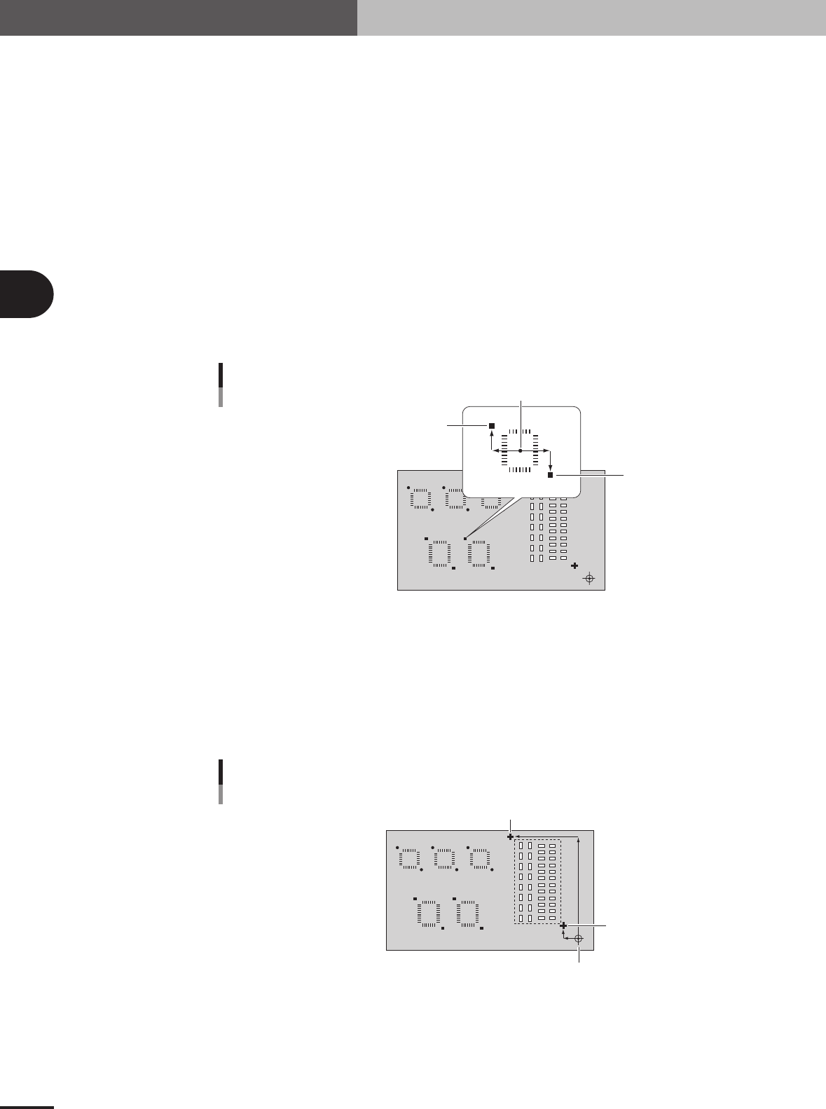
The point fiducial function uses a set of two fiducial marks diagonally located across the land
patterns on which you want to improve mounting position accuracy. It is okay if these two marks
are different in shape, but use the same marks for the same type of component.
Point fiducial marks
Mounting center
Mark 1 (X1, Y1)
Mark 2 (X2, Y2)
23411-5E-20
2. Local fiducial function
The local fiducial function improves the mounting position accuracy of two or more components
within a specified area, by using a pair of fiducial marks. This function is also effective in correct-
ing the mounting position errors when two or more different types of PCBs are supplied on the
same transfer pallet. The local fiducial marks must be arranged diagonally across the specified
area, but can be different in shape from each other.
Local fiducial marks
PCB origin or block offset
Mark 1 (X1, Y1)
Mark 2 (X2, Y2)
23412-5E-20
3 -21
3
Creating the PCB data
3. Creating the PCB information
3. 4-point fiducial function
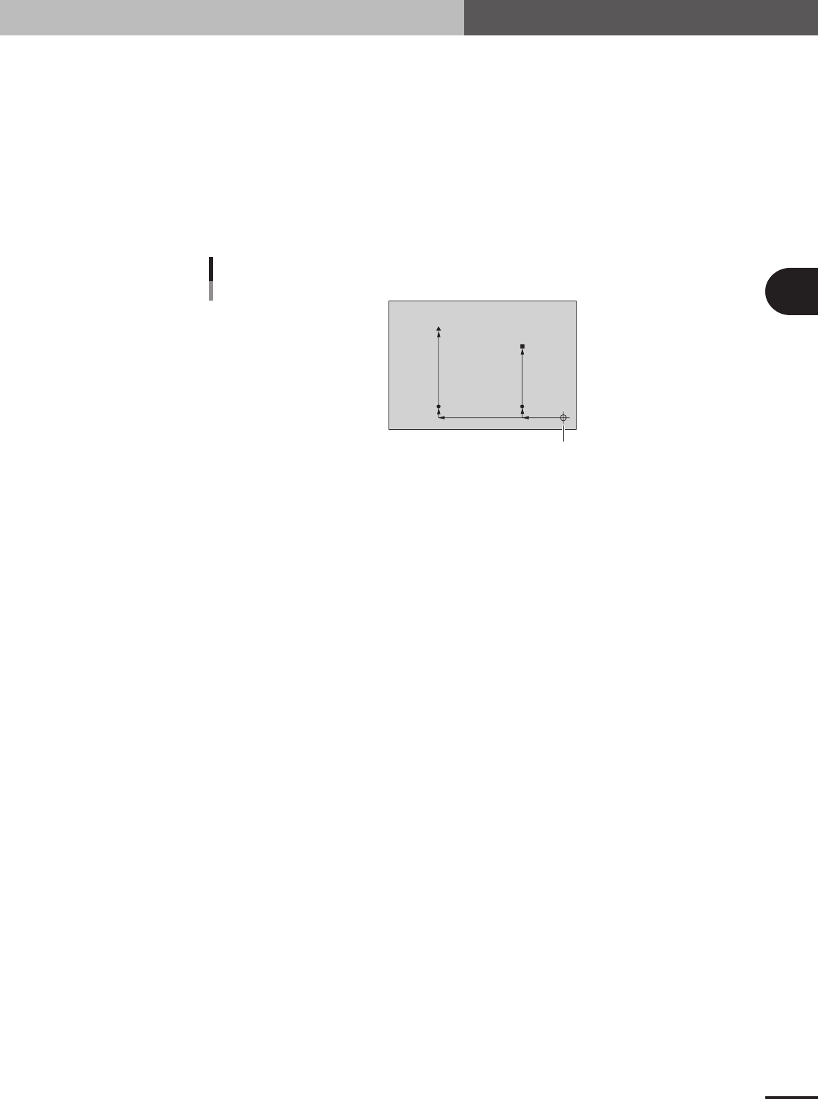
The "4-point fiducial" function is used to enhance the mounting position accuracy by recognizing 4
fiducial marks provided on a PCB. This function is effective in the following cases.
• PCBs with 4 or more fiducial marks which meet the conditions
• Large PCBs
• PCBs made of materials which tend to expand, flex or warp.
(paper phenol, paper, glass epoxy, other flexible materials)
The 4-point fiducial data settings are basically the same as those for point fiducial and local
fiducial marks. However, because the 4-point fiducial function requires 4 XY coordinate points,
you must use two data lines ("4Local-M" and "4Local-S") on the Offset tab screen in order to
register one set of 4-point fiducial marks.
4-point fiducial marks
(-50, 10)
(-200, 10)
(-50, 150)
(0, 0)
(-200, 200)
Mark 3
PCB origin
Mark 2
Mark 4
Mark 1
23413-5E-20
3
Creating the PCB data
3-22
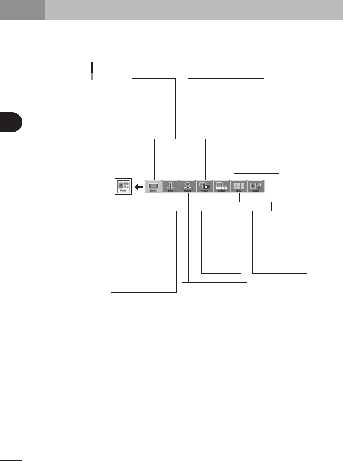
4. Creating the component information
This section explains how to create component data. Component data has various parameters for each
of the component names registered as illustrated below. To set these parameters, it is convenient to
copy sample data of a component with a similar shape from the database and then edit only the
different parameters.
Component name
Comment
Component information parameter
Alignment Group
Alignment Type
Required Nozzle
Package
Feeder Type
Dump Way
Retry Times
Conveyor X Speed
Database Number
(Library Name)
Feeder Set No.
Position Definition
Y (mm)
Pick Angle
Pick Height
Pick Timer sec
Pick Speed
XY Speed
Pick&Mount Vacuum Check
Pick Vacuum
Pick Start
Pick Action
Pick Tango
Mount Height
Mount Timer
Mount Speed
XY Speed
Pick&Mount Vacuum Check
Mount Vacuum
Mount Action
Mount Tango
(Alignment Group)
(Alignment Type)
Body Size XY
Body Size Z
Ruler Offset
Ruler Width
Lead Number
Lead Width
ReflectLL
etc.
(Package)
(Feeder Type)
Comp Amount
Tray Amount XY
Count Out Stop
etc.
Alignment Module Fore, Back
Light Main, Coax, Side
Lighting Level
Auto Threshold
Comp. Threshold
Comp. Tolerance
Search Area
Datum Angle
Comp. Intensity
Multi MACS
Alternative Parts
Parts Group No.
Use Feeder Optimize
23416-5E-20
Reference
Parameters displayed somewhat differ depending on the selected component type and package style.