M3plus_OperationManual_e.pdf - 第88页
3 - 23 4. Creating the component information 3 Creating the PCB data 4.1 Creating procedure After selecting the PCB name, press the [Parts] button in the main menu button area to open the component information screen. En…
3
Creating the PCB data
3-22
4. Creating the component information
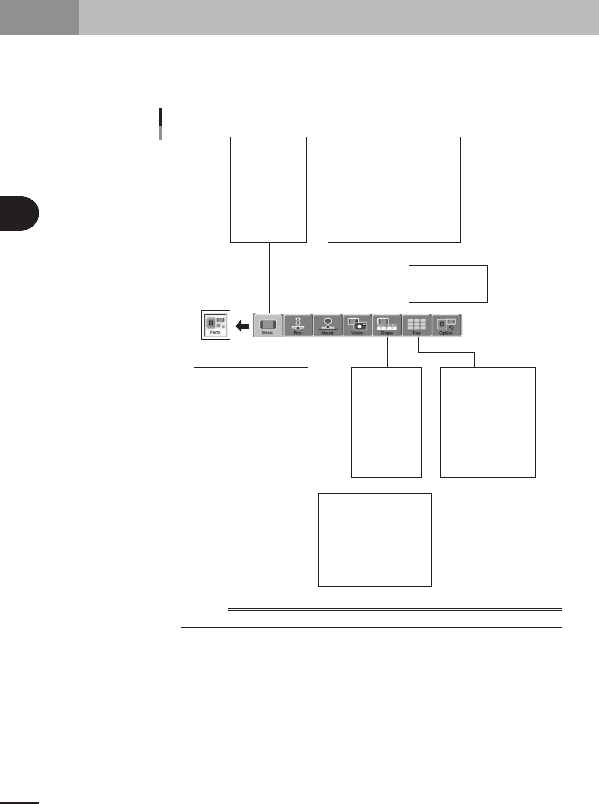
This section explains how to create component data. Component data has various parameters for each
of the component names registered as illustrated below. To set these parameters, it is convenient to
copy sample data of a component with a similar shape from the database and then edit only the
different parameters.
Component name
Comment
Component information parameter
Alignment Group
Alignment Type
Required Nozzle
Package
Feeder Type
Dump Way
Retry Times
Conveyor X Speed
Database Number
(Library Name)
Feeder Set No.
Position Definition
Y (mm)
Pick Angle
Pick Height
Pick Timer sec
Pick Speed
XY Speed
Pick&Mount Vacuum Check
Pick Vacuum
Pick Start
Pick Action
Pick Tango
Mount Height
Mount Timer
Mount Speed
XY Speed
Pick&Mount Vacuum Check
Mount Vacuum
Mount Action
Mount Tango
(Alignment Group)
(Alignment Type)
Body Size XY
Body Size Z
Ruler Offset
Ruler Width
Lead Number
Lead Width
ReflectLL
etc.
(Package)
(Feeder Type)
Comp Amount
Tray Amount XY
Count Out Stop
etc.
Alignment Module Fore, Back
Light Main, Coax, Side
Lighting Level
Auto Threshold
Comp. Threshold
Comp. Tolerance
Search Area
Datum Angle
Comp. Intensity
Multi MACS
Alternative Parts
Parts Group No.
Use Feeder Optimize
23416-5E-20
Reference
Parameters displayed somewhat differ depending on the selected component type and package style.
3 -23
4. Creating the component information
3
Creating the PCB data
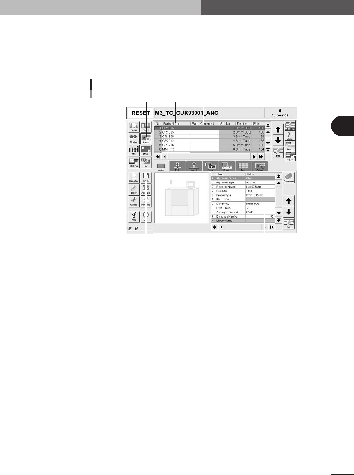
4.1 Creating procedure
After selecting the PCB name, press the [Parts] button in the main menu button area to
open the component information screen. Enter the component name and comment in the
data No. list on the upper part of the screen, and set the parameters in the right lower list,
as explained below.
1
Press the [Parts] button to open the component information screen.
Step 1 Step 2 Step 3
Step5
Step 4
Step 7
Component information screen
27411-5E-20
2
Enter the component name in the Part Name column.
Enter the name printed on the tape reel or on the component itself within 20 alphanu-
meric characters. A space cannot be included in the name.
3
Enter a comment.
Type any desired comment in the Parts Comment column as necessary. You can omit
entering comments here.
4
Set the parameters.
While selecting the [Basic], [Pick], [Mount], [Vision], [Shape] tabs and so forth, set the
necessary parameters in the right lower list.
5
Adjust the parameters in the Parts Adjust mode.
Press the [Adjust] button to open the Parts Adjust screen that allows you to adjust or
check the parameters of the selected component. (For more details, see "4.9 Parts
Adjust mode" in this chapter.)
6
Repeat the above steps for other components.
Repeat the same procedure from step 2 to register all components to be mounted on
the PCB.
7
Save the data.
Press the [Save] button to store the data.
3 -24
3
Creating the PCB data
4. Creating the component information
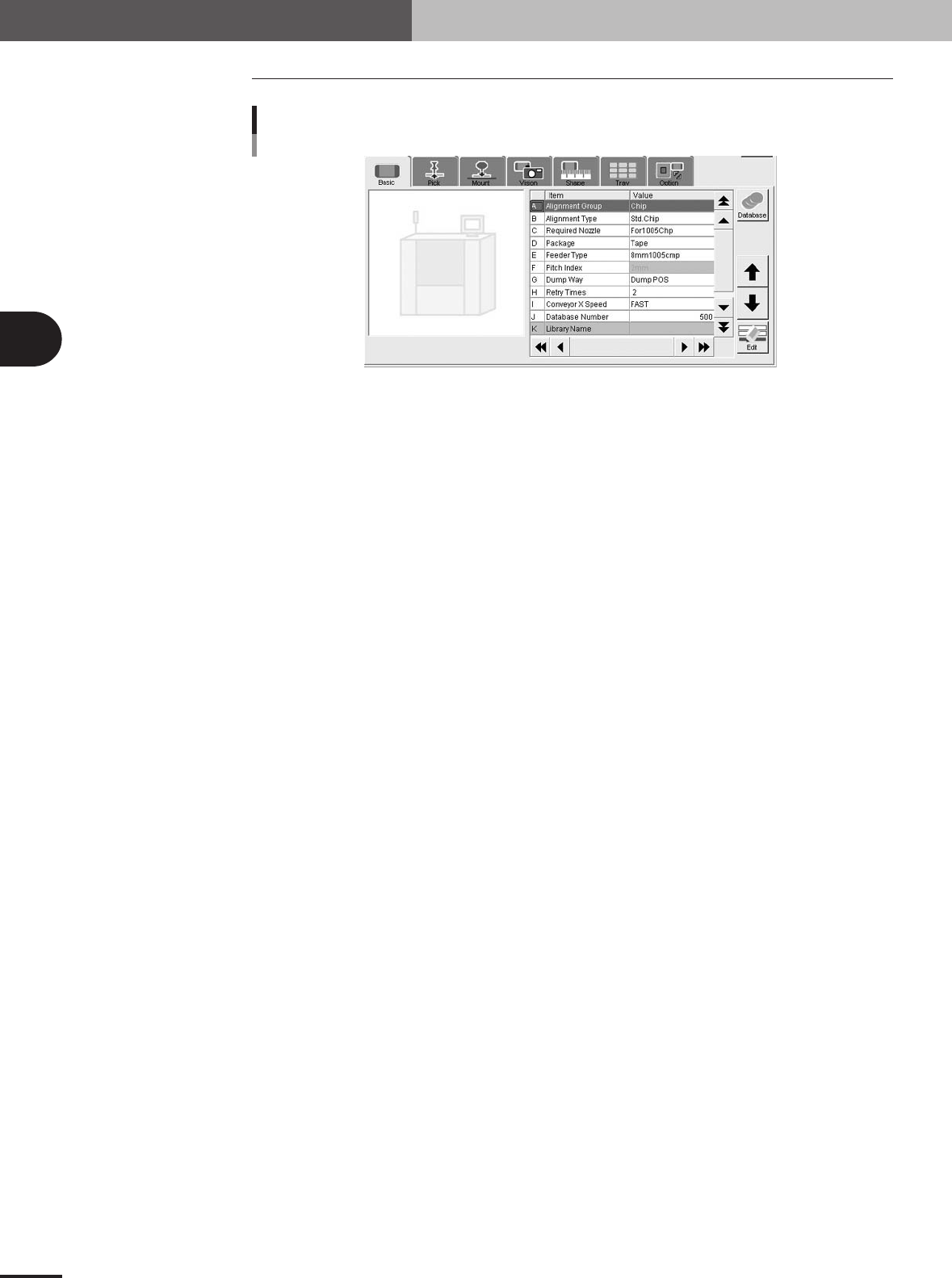
4.2 Basic parameters
Basic parameters
27412-5E-20
A: Alignment Group
Select from "Chip", "IC", "Ball", "Connector" or "Special".
B: Alignment Type
Specify the type of component by referring to the descriptions below.
Chip
• Std.Chip (Standard chip)
This setting does not identify the component, but detects the four corners of the component and
then calculates the center and angle of the component. Select this setting first when recognizing
box type chips. If the component cannot be recognized by this setting, try using "Sp.Chip" or
"Small Chip".
•Melf Chip
This is specially for Melf chips.
• Bare Chip
This is specially for bare chips.
• Cylinder
This is suited for components with a cylindrical shape and no direction.
• Sp.Chip (Special chip)
This setting has a parameter used to recognize "Lead Width" in addition to the "Std.Chip" setting.
Select this to recognize box type chips which cannot be recognized correctly by the "Std.Chip"
setting. If it is still difficult to recognize the component by this setting, try with "Odd.2Ends".
• Small Chip
This is suited for small chip components such as 0603 whose light-reflecting area is smaller than
the actual size.
IC
• Odd.2Ends
This mode has a parameter used for recognizing the lead width and length by using "LeadWidth"
and "ReflectLL." in addition to the "Std.Chip" mode. This mode is suited for recognizing box type
chips which cannot be recognized by "Std.Chip" or "Sp.Chip".
• Mini Tr/SOT
This mode is for mini mold components with the same shape leads in the N and S direction, but
whose number of leads in each direction is different.
•P-Tr
This mode is for components having leads in the N and S direction, and whose number of leads in
each direction is different like "Mini-Tr/SOT", and also the shape of opposing leads is different.
• SOP
This is for components having the same shape leads and same number of leads in the E and W
direction, and whose leads protrude out from the molded body.