M3plus_OperationManual_e.pdf - 第93页
3 - 28 3 Creating the PCB data 4. Creating the component information G: Dump Way This specifies the location where a component will be dumped if an error such as recognition error has occurred. Set to "Dump POS"…
3 -27
4. Creating the component information
3
Creating the PCB data
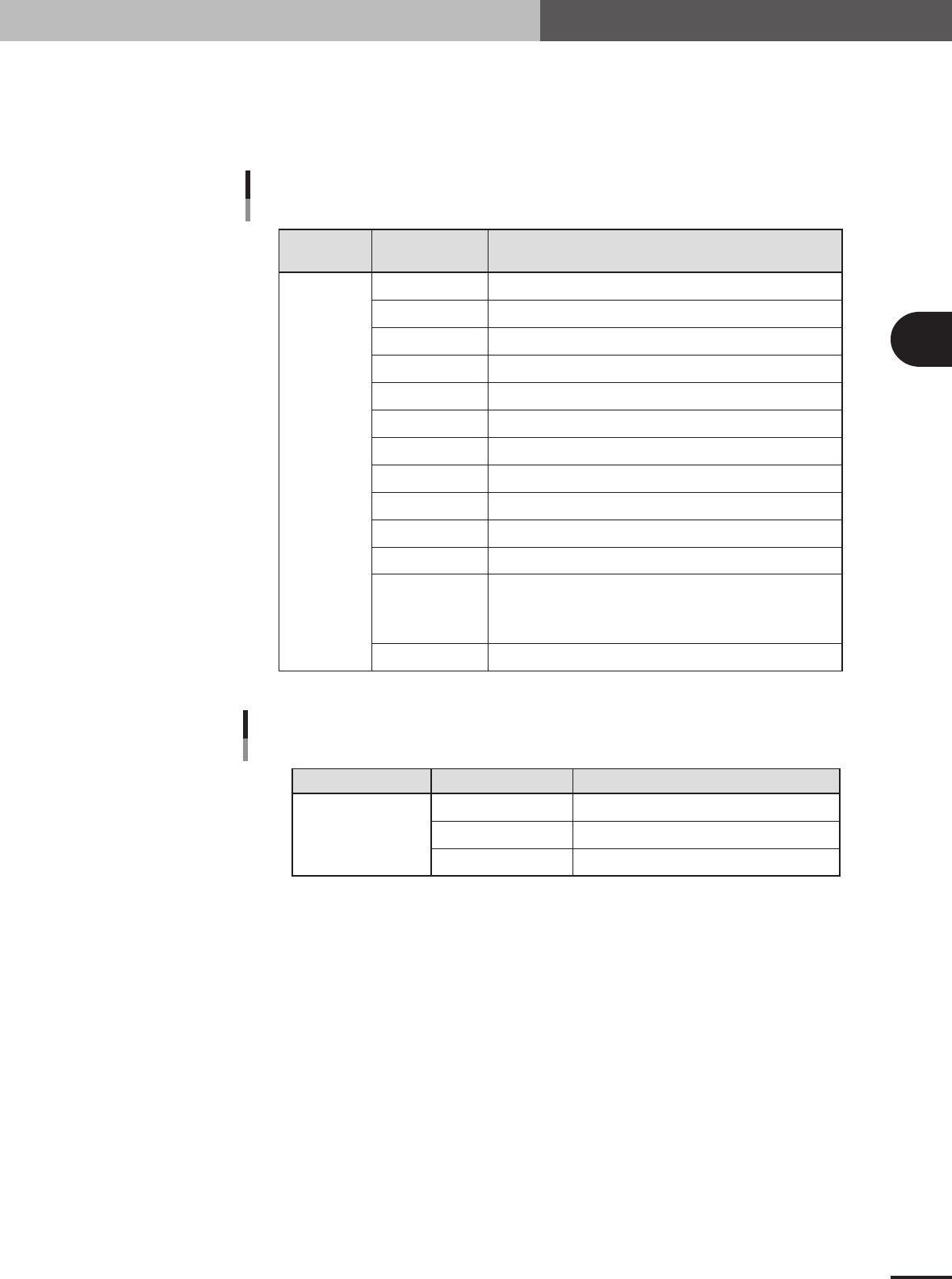
E: Feeder Type
Select the specific feeder type to be used for component supply. Selectable items differ depending
on the Package parameter setting. Refer to the table below to make a selection. When the Package
parameter is set to "Stick" or "Tray", see "4.7 Setting the stick feeder component data" or "4.8
Setting the tray component data" in this chapter.
Comp.
Package setting
Tape feeder or bulk cassette feeder type Feeder Type setting
Feeder Type settings
when "Package" is set to "Tape"
Tape
8mm tape feeder (except for 1005, 0603 chip)
8mm tape feeder (for 1005 chip)
8mm tape feeder (for 1005, 0603 chip)
12mm tape feeder (standard pitch)
12mm tape feeder (long pitch)
16mm tape feeder
24mm tape feeder
32mm air-driven feeder with sticky tape
32mm embossed air-driven feeder
44mm embossed air-driven feeder
56mm embossed air-driven feeder
Select these settings when using a tape feeder other than the above.
Note that you must make necessary settings on the <3/1/A5 FEEDER
SPEC. INF> screen. For the setting procedure, refer to the mounter
service manual.
8mmTape
8mm1005cmp
8mm0603cmp
12mmEmboss
12mmLongPitch
16mmEmboss
24mmEmboss
32mmSticky
32mmEmboss
44mmEmboss
56mmEmboss
Tape-A to D
Spear1 to 10
25403-5E-20
Comp. Package setting Tray feeder typeFeeder Type setting
Feeder Type setting
when "Package" is set to "Tray"
Tray
Tray shuttle feeder (TSF1)
Not available
Not available
Fix. TF
Ext. TC
Auto TC
25404-5E-20
3 -28
3
Creating the PCB data
4. Creating the component information
G: Dump Way
This specifies the location where a component will be dumped if an error such as recognition error
has occurred. Set to "Dump POS" for chip components and small components.
H: Retry Times
This determines how many times the machine will retry the same operation if an error such as a
recognition error has occurred. The number of retries can be set from "NO RETRY" to "14". When
this retry setting is greater than the machine data retry setting, the machine data has priority.
I: Conveyor X Speed
The conveyor X-axis moving speed can be selected. If components tend to move or slide (such as
tall components) just after mounted on the PCB due to the X-axis movement, set this parameter to
a lower speed to prevent it. Select the optimum speed from among "FAST", "MEDIUM", "SLOW"
and "VERY SLOW".
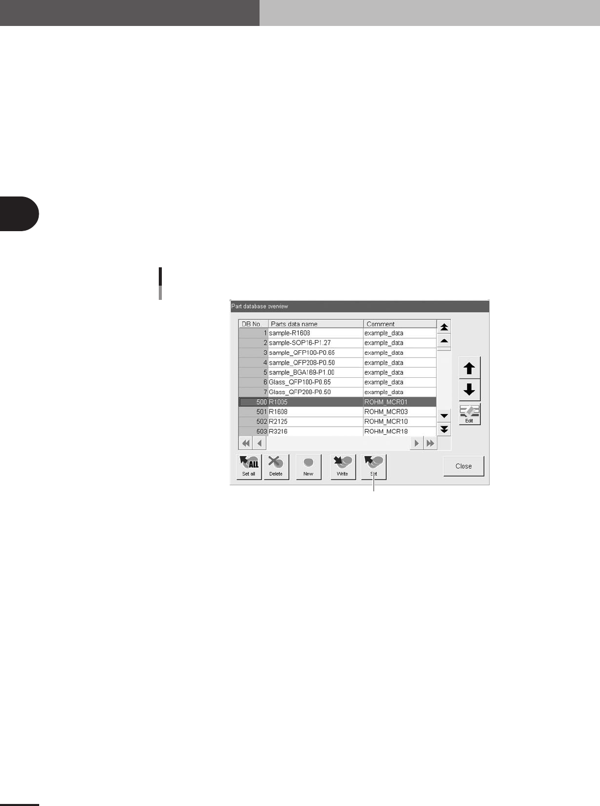
J: Database number
Shows the database number when the parameter values were copied from the database.
When you want to copy the parameter values from the database, press the [Database] button to
open the database list. Then select the copy source data and press the [Set] button to make a copy.
Press this button.
Database set
27413-5E-20
K: Library Name
The name of the component data library is displayed. This data library can be managed in the
machine or on a PC connected to LAN. (When using the data library, see "3. Creating XML
library" in chapter 6.)
3 -29
4. Creating the component information
3
Creating the PCB data
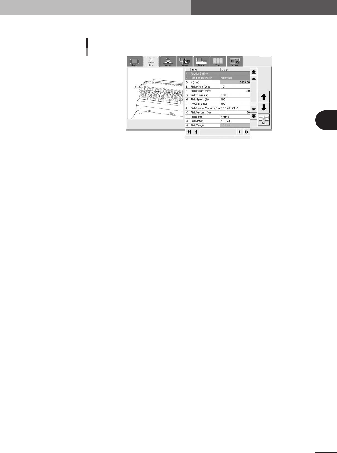
4.3 Pick parameters
Pick parameters
27414-5E-20
A: Feeder Set No.
Enter the feeder set number of the position on the feeder plate (feeder knockpin position) at which
the feeder is installed. This parameter setting is unnecessary when the "Use feeder optimize"
parameter is set to "Yes". When using a tray shuttle feeder (TSF1), refer to section 4.10, "Using
component feeders other than tape feeders".
B: Position Definition
Set to "Automatic" when the Package parameter is set to "Tape" or "Bulk". (The component pickup
position will be calculated automatically.) Set to "Teaching" when using a stick feeder or tray
shuttle feeder (TSF1). (See "4.10 Using component feeders other than tape feeders" in this chap-
ter.)
D: Y (mm)
Enter the position at which the head picks up the component from the feeder. These parameters are
skipped when the Position Definition parameter is set "Automatic".
When stick feeders or tray shuttle feeder (TSF1) are used, enter the pickup position by teaching.
(See "4.10 Using component feeders other than tape feeders" in this chapter.)
E: Pick Angle (deg)
• This parameter specifies the angle through which the mounter head rotates to pick up a component
on the feeder. This setting determines the orientation of the component (recognition reference)
when it is recognized and displayed on the operation monitor. Normally, set this parameter to 0
deg for horizontally long components in the loading position on the feeder, and set to 90 deg for
vertically long components.
•When using a bulk cassette feeder, always set this parameter to 90°.
• The pickup angle for transistors must be specified so that their leads face the NS directions. Set
this parameter to 0 deg for vertically long components in the loading position on the feeder, and set
to 90 deg for horizontally long components. Select the correct pickup angle by referring to the
table below.
• The pickup angle for SOP components must be specified so that their leads face the EW directions.
Set this parameter to 0 deg for horizontally long components in the loading position, and set to 90
deg for vertically long components. Select the correct pickup angle by referring to the table below.
• The pickup angle of connectors must be specified so that their leads face the E direction. Select the
correct pickup angle according to the loading position of the component as shown in the table
below.