M3plus_OperationManual_e.pdf - 第97页
3 - 32 3 Creating the PCB data 4. Creating the component information 4.4 Mount parameters Mount parameters 27415-5E-20 A: Mount Height (mm) This is the Z-axis height offset value used when the head lowers to mount a comp…

3 -31
4. Creating the component information
3
Creating the PCB data
J: Pick&Mount Vacuum Check
Set this parameter to "NORMAL CHK" in most cases. If you want to check pickup errors and
mount errors more strictly (head return without mounting the component), set to "SPECIAL CHK".
For example, when using QFP components and you want to check pickup errors and mount errors
(erroneous head return without mounting the component) more strictly, set this parameter to
"SPECIAL CHK".
n
NOTE
When the Pick&Mount Vacuum Check parameter is set to "NORMAL CHK", the machine controls the ascent
timing of the head from the lowered position during component pickup or mounting. This parameter setting is
valid only when the Vacuum Check parameter on the Board tab screen is set to "Check".
K: Pick Vacuum
This is the reference vacuum pressure used for checking the pickup vacuum level. Use the default
setting and adjust it as needed in the Parts Adjust mode. (See "4.9.1 Parts Adjust mode" in this
chapter.)
L: Pick Start
This parameter specifies the timing to start vacuum generation when the head picks up a compo-
nent. When set to "Normal", vacuum generation starts before the head moves down. When set to
"Bottom", vacuum generation start after the head has moved down. Set this parameter to "Normal"
in most cases.
M: Pick Action
This specifies the nozzle decent movements during component pickup. Set this parameter to
"Normal" in most cases. Setting this parameter to "DETAIL" allows you to set the Pick Tango
parameter.
N: Pick Tango
Set this parameter to "NORMAL" in most cases. When higher accuracy is required to pick up a
small component, set to "INTOL". (This parameter can be selected only when the Pick Action
parameter is set to "DETAIL".
3 -32
3
Creating the PCB data
4. Creating the component information
4.4 Mount parameters
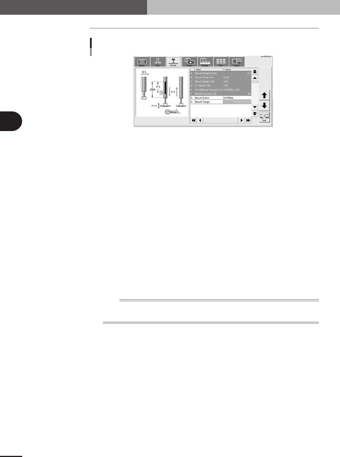
Mount parameters
27415-5E-20
A: Mount Height (mm)
This is the Z-axis height offset value used when the head lowers to mount a component. Set this
parameter to "0.0" in normal operation.
If you want to lower the Z-axis height during component mounting, enter a plus value in the Pick
Height column. Conversely, if you want to raise the Z-axis height, enter a minus value.
B: Mount Timer
This parameter specifies the time duration (in seconds) for which the head stays in the lowered
position after detecting the reference mount vacuum pressure when mounting a component. In most
cases, it is okay to set this parameter to "0.00". If pickup or mount operation is unstable, set a
longer timer value.
C: Mount Speed (%)
This is related to the Pick Speed setting in the Pick parameters. (The setting value changes simulta-
neously as the Pick Speed setting is changed.)
D: XY Speed (%)
This is related to the XY Speed setting in the Pick parameters. (The setting value changes simulta-
neously as the XY setting in the Pick parameters is changed.)
E: Pick&Mount Vacuum Check
Set this parameter to "NORMAL CHK" in most cases. If you want to check pickup errors and
mount errors more strictly (head return without mounting the component), set to "SPECIAL CHK".
n
NOTE
When the Pick&Mount Vacuum Check parameter is set to "NORMAL CHK", the machine controls the ascent
timing of the head from the lowered position during component pickup or mounting. This parameter setting is
valid only when the Vacuum Check parameter on the Board tab screen is set to "Check".
F: Mount Vacuum
This is the reference vacuum pressure used for checking the mount vacuum level. Use the database
default setting and adjust it as needed in the Parts Adjust mode. (See "4.9.1 Parts Adjust mode" in
this chapter.)
G: Mount Action
This is related to the Pick Action setting in the Pick parameters. (The setting value changes
simultaneously as the Pick Action setting is changed.)
H: Mount Tango
Set this parameter to "NORMAL" in most cases. When higher accuracy is required to pick up a
small component, set to "INTOL". (This parameter can be selected only when the Pick Action
parameter is set to "DETAIL".
3 -33
4. Creating the component information
3
Creating the PCB data
4.5 Vision parameters
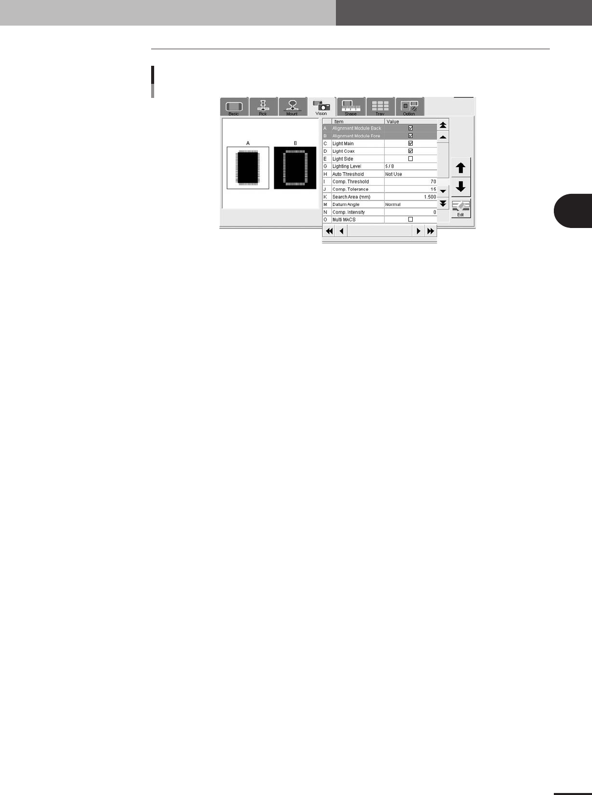
Vision parameters
27416-5E-20
A, B: Alignment Module Fore, Back
This parameter specifies the lighting method for recognizing a component. Use the default settings
("Fore" and "Back") in most cases.
C to E: Light Main, Coax, Side
Select the lighting methods that best match the component. Use the default setting ("Light Main" and
"Light Coax" selected) in most cases. When "Alignment Type" is set to "BGA" and you want to
check nicks on the BGA leads, select "Side" only.
G: Lighting Level
This parameter specifies the reflected light brightness. Normally, use the default setting and then
optimize it in the Parts Adjust mode.
H: Auto Threshold
Shows a threshold level for standard chip component that was automatically calculated from the
acquired image.
I: Comp. Threshold
This parameter specifies the threshold level used to discern the light-reflecting part (lead) from the
background during component recognition. Normally, use the default setting and then optimize it in
the Parts Adjust mode. This parameter is skipped for BGA components.
J: Comp. Tolerance
This parameter specifies the tolerance for recognizing a component, in an allowable error percentage
of 0 to 100%. The larger the percentage, the greater the tolerance. First use the default setting and
then gradually increase it while checking the recognition status in the Parts Adjust mode.
K: Search Area (mm)
This parameter specifies the area within which the component leads are searched. As this value is set
larger, the search area is extended, but with a loss in the image processing speed. First use the default
setting and then optimize it in the Parts Adjust mode.
M: Datum Angle
This parameter specifies the angle of component shape definition. Use the default setting in most
cases.
N: Comp. Intensity
This parameter specifies the threshold level used to measure the intensity in the outline area of a
component after it is successfully identified by normal vision recognition. If the measured intensity
level is lower than this threshold, the recognition result is viewed as an error. (This parameter is valid
only when "Alignment Type" is set to "Std.Chip".)
O: Multi MACS
Set whether to use the Multi MACS correction. Mark the check box when using this function.