M3plus_OperationManual_e.pdf - 第99页
3 - 34 3 Creating the PCB data 4. Creating the component information 4.6 Shape parameters Set these parameters after specifying "Alignment Type". If "Alignment Type" is unde- fined, the following para…
3 -33
4. Creating the component information
3
Creating the PCB data
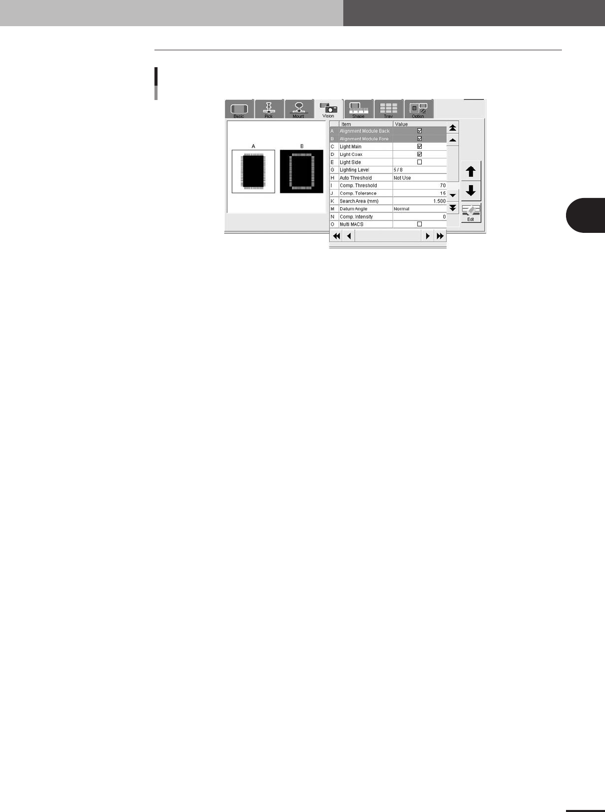
4.5 Vision parameters
Vision parameters
27416-5E-20
A, B: Alignment Module Fore, Back
This parameter specifies the lighting method for recognizing a component. Use the default settings
("Fore" and "Back") in most cases.
C to E: Light Main, Coax, Side
Select the lighting methods that best match the component. Use the default setting ("Light Main" and
"Light Coax" selected) in most cases. When "Alignment Type" is set to "BGA" and you want to
check nicks on the BGA leads, select "Side" only.
G: Lighting Level
This parameter specifies the reflected light brightness. Normally, use the default setting and then
optimize it in the Parts Adjust mode.
H: Auto Threshold
Shows a threshold level for standard chip component that was automatically calculated from the
acquired image.
I: Comp. Threshold
This parameter specifies the threshold level used to discern the light-reflecting part (lead) from the
background during component recognition. Normally, use the default setting and then optimize it in
the Parts Adjust mode. This parameter is skipped for BGA components.
J: Comp. Tolerance
This parameter specifies the tolerance for recognizing a component, in an allowable error percentage
of 0 to 100%. The larger the percentage, the greater the tolerance. First use the default setting and
then gradually increase it while checking the recognition status in the Parts Adjust mode.
K: Search Area (mm)
This parameter specifies the area within which the component leads are searched. As this value is set
larger, the search area is extended, but with a loss in the image processing speed. First use the default
setting and then optimize it in the Parts Adjust mode.
M: Datum Angle
This parameter specifies the angle of component shape definition. Use the default setting in most
cases.
N: Comp. Intensity
This parameter specifies the threshold level used to measure the intensity in the outline area of a
component after it is successfully identified by normal vision recognition. If the measured intensity
level is lower than this threshold, the recognition result is viewed as an error. (This parameter is valid
only when "Alignment Type" is set to "Std.Chip".)
O: Multi MACS
Set whether to use the Multi MACS correction. Mark the check box when using this function.
3 -34
3
Creating the PCB data
4. Creating the component information
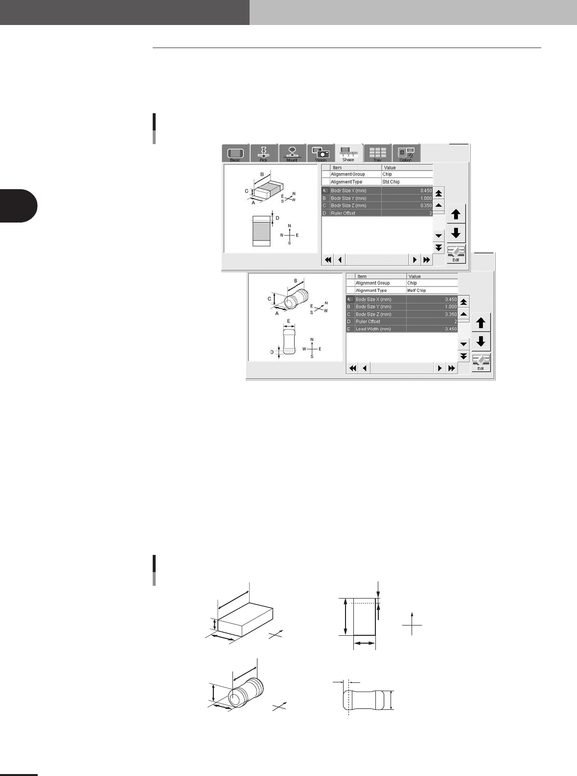
4.6 Shape parameters
Set these parameters after specifying "Alignment Type". If "Alignment Type" is unde-
fined, the following parameters are not displayed.
Chip components
Chip components
27417-5E-20
A, B: Body Size X, Body Size Y
Enter the correct dimensions (mm) measured with a vernier caliper or micrometer.
C: Body Size Z
Enter the correct thickness (mm) measured with a vernier caliper or micrometer.
D: Ruler Offset
This parameter specifies the distance in pixels, from the end of the component to an imaginary
ruler line used to measure the lead width. Use the default setting in most cases.
E: Lead Width
Enter the width of the leads provided on both ends of the component. This can be checked later in
the Parts Adjust mode. (Standard box type chip components do not use this parameter.)
N
S
E
W
A
C
B
N
S
W
E
A
B
D
N
S
E
W
C
A
B
E
D
Top view
A : Body Size X
B : Body Size Y
C : Body Size Z
D : Ruler Offset
A : Body Size X
B : Body Size Y
C : Body Size Z
D : Ruler Offset
E : Lead Width
Shape parameters for chip components
23417-5E-20
3 -35
4. Creating the component information
3
Creating the PCB data
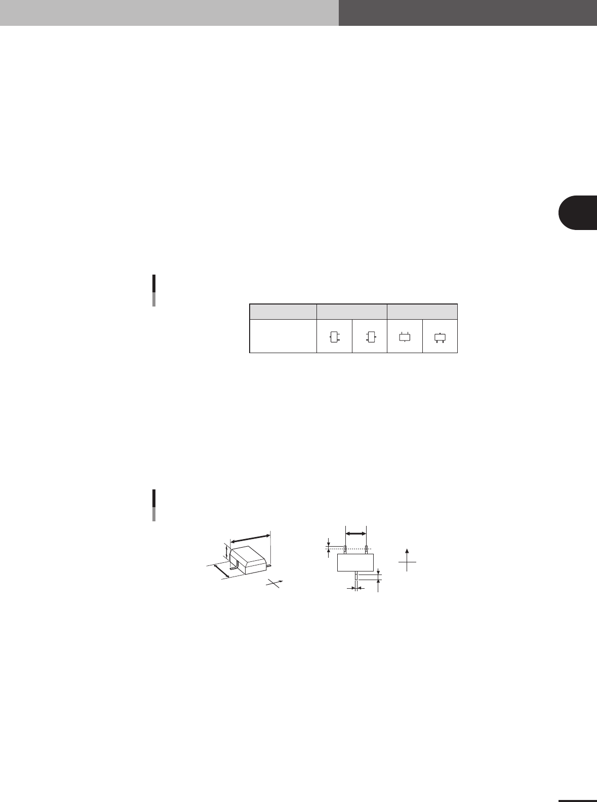
Mini-mold transistors and SOT
A, B: Body Size X, Body Size Y
Enter the correct dimensions (mm) including the leads, measured with a vernier caliper or mi-
crometer.
C: Body Size Z
Enter the correct thickness (mm) measured with a vernier caliper or micrometer.
D: Ruler Offset
Enter the distance in pixels from the end of the component to an imaginary line used to measure
the lead width and pitch. Use the default setting in most cases.
E: Ruler Width
Enter the width of an imaginary line used to measure the lead width and pitch. Set this parameter
to "1 to 2" for components with a lead length shorter than 0.3mm, and to "2 to 3" for components
with a lead length longer than 0.3mm. Use the default setting in most cases.
F, G: Lead Number NS
Enter the number of leads existing in the N and S directions.
Pickup angle
Loading position
0° 90°
NSNS
N
S
N
S
Mini-mold transistor and SOP lead direction
25408-5E-20
H, I: Lead Pitch NS
Enter the correct lead pitch (lead-to-lead spacing).
J: Lead Width
Enter the correct lead width
K: ReflectLL
Enter the projected length of leads which reflect light during recognition. Use the default setting in
most cases.
N
S
E
W
B
C
A
N
S
E
W
H
K
D
J
A : Body Size X
B : Body Size Y
C : Body Size Z
D : Ruler Offset
H : Lead Pitch
J: Lead Width
K: Reflect LL
Bottom view
Shape parameters for mini-mold transistors
23420-5E-20