SM_Series_EN.pdf - 第3页
Multi-F unctional Plac er P anorama view The SM482PL US can be applied to components from 0603 microchips to □ 22mm IC components by applying the on-the -y recognition technology patented b y Hanwha, which enables compo…
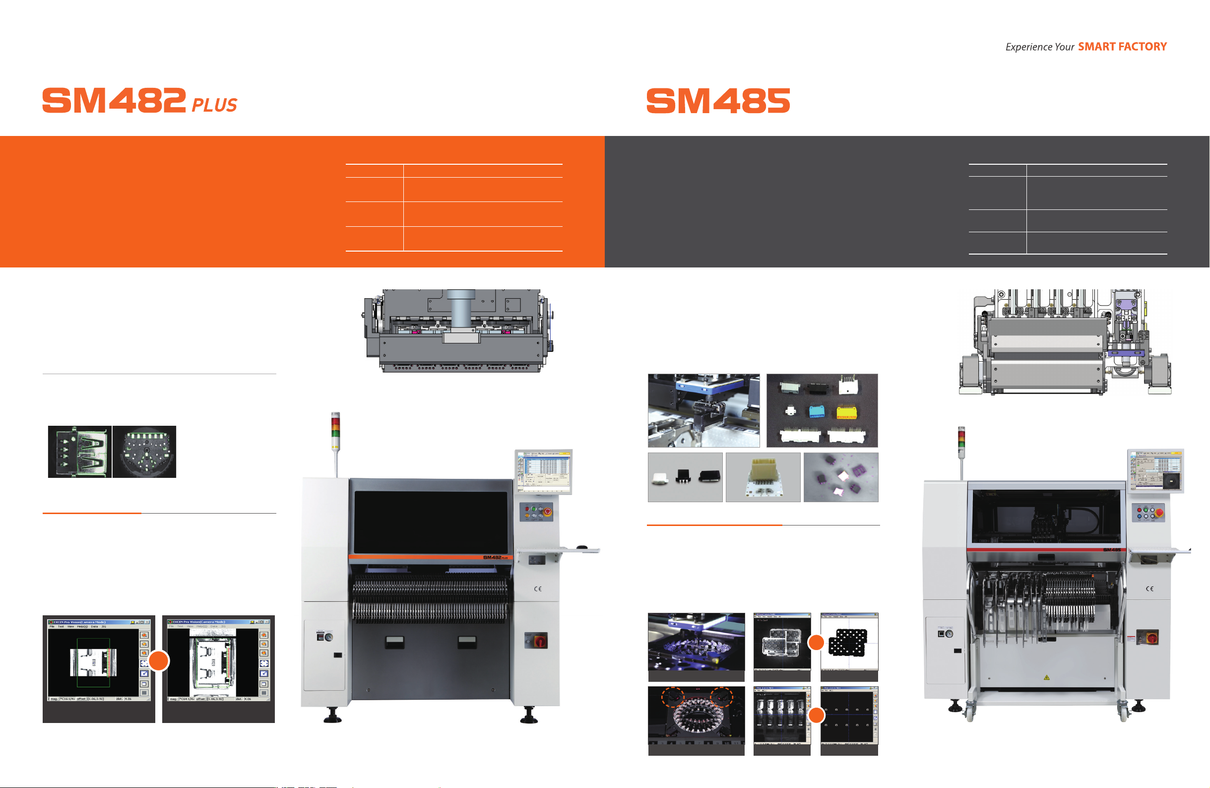
Multi-Functional Placer
Panorama view
The SM482PLUS can be applied to components from 0603 microchips to
□
22mm IC components by applying the on-the-y recognition technology
patented by Hanwha, which enables component placement at the highest
speed among all medium speed component placers. In addition, it can
recognize components of
□
42mm with 0.4mm fine pith with a 45mm
camera by applying a high pixel Camera system to the Fix camera. It also
allows high precision (30 micron) placement of IC components and provides
a polygon recognition algorithm for easy registration of components of
complicated shapes.
Features
Placement Speed
Chip 30,000CPH (Optimal)
Applicable
Component
0603 ~
□
22mm (h12mm) (Fly)
~ Max.
□
55mm, L75 (h15mm) (Fix)
Placement
Accuracy
±40
㎛
@ Cpk ≥ 1.0 /Chip,
±30
㎛
@ Cpk ≥ 1.0 /QFP
Applicable PCB
L460xW400x1Lane (Standard)
L1,200xW510x1Lane (Option)
Powerful Camera algorithm
Increases the recognition accuracy using the component image
noise removal function and auto-teaching function. The Fly camera
helps recognize and calibrate the components including Chip, TR,
BGA, QFP, etc., while moving them to the placement position after
pickup.
For components whose size exceeds the FOV of a camera, the
panorama view function that combines split component images
into one is used. The solution optimized for irregular shaped SMD
components is provided by teaching the pickup/placement position
easily.
●
Automatic Real Time Pickup Position Calibration System
●
Polygon Function
Abstracts and recognizes a component wholly
General Image of Large
Component Pickup
Combined Panoramic Image
▶
6Spindle x 1Gantry
Wide Ranged Component Placer
The SM485 is a wide range chip mounter that allows high-speed placement of
small components as well as precise placement of odd-shaped components with
4 sets of high-speed spindles and 1 set of precision spindle with back-light system
and force control function. It can place various odd-shape components from
0402 chips up to
□
55mm IC components(H26mm), Long connectors of 150mm,
Shield cans, Bare chips, Insert components, etc. In addition, The SM485 provides
an all-in-one solution that allows high quality placement and management of
components from chips to odd-shaped components without adding an extra
expensive machine.
BeforeLaser lighting After
▶
BeforeBacklight After
▶
Features
Placement Speed
22,000 CPH
Applicable
Component
0402 ~
□
21mm (h15mm) (Fly)
~
□
55mm (h26mm) (Fix)
L150mm x 25mm
Placement
Accuracy
±40
㎛
@ Cpk ≥ 1.0 /Chip,
±30
㎛
@ Cpk ≥ 1.0 /IC
Applicable PCB
L460xW400x1Lane (Standard)
L740xW460x1Lane (Option)
Optimum solution for the placement of
Insert components
Various lighting for component recognition
Provides various gripper nozzles and force control function to place
precisely odd-shaped components of various sizes and heights.
Allows precise placements of insert components and bare chips
that need to control the pressure in z-axis direction for placements.
Allows more precise placement through shadow recognition by
applying backlight for the accurate recognition of components such
as shield cans with high reectivity. In addition, provides the laser
lighting as a option to recognize pins of inserted components more
accurately.
4high-speed+1high precision Spindlex1Gantry