00192156-04.pdf - 第60页
Maintenance Maintenance Instr uctions F 9 4-monthly maintenance jobs 03/2003 US Edition 60

Maintenance Instructions F Maintenance
03/2003 US Edition 9 4-monthly maintenance jobs
59
9
You will need the following tools, equipment and consumables for the 4-monthly maintenance. 9
– Pliers in the service box (article no.: 00346929-01)
– Short-bristled brush
– Set of hexagon socket spanners
– Lint-free cottonwool buds (article no.: 00352931-02)
– Ethyl alcohol
– Lint-free cloths
– ISOFLEX TOPAS NCA52 grease (article no. 1 kg can, 00328369-01, 50g tube, 00330850-01)
– Unisilkon L250L (article no.: 00310259-01)
– Oil dispenser with Structovis GHD (article no.: 00367071-01)
– Set of clean sleeves
– Set of clean valve plungers
– New Z-toothed belt, if required (article no.: 00334936-01)
– New distributor, if required (article no.: 00319827-02)
– New O-ring for the turning station, if required (article no.: 00320043-01)
– New toothed belt for the turning station, if required (article no.: 00320041-01).
9
9.1 Fitted placement heads
Placement machines from the F family can have the following placement heads: 9
9
SIPLACE 8000 10000 DLM 1 IC CAN bus
F4 x (1x) x (1x)
F4-6 x (1x) x (1x)
F5 x (1x) x (1x)
F5 HM x x x (1x)
Maintenance Maintenance Instructions F
9 4-monthly maintenance jobs 03/2003 US Edition
60

Maintenance Instructions F Maintenance
03/2003 US Edition 9 4-monthly maintenance jobs
61
Dismantle front part of head 9
: Use the "Single Functions" menu to return the nozzles of every Collect&Place head to the noz-
zle changer.
: Switch the placement system off at the main switch.
Follow the correct shut-down routine. 9
9
9
Remember to follow the ESD regulations.
9
9
: Cover the feeder area to protect the feeder modules and front part of the head.
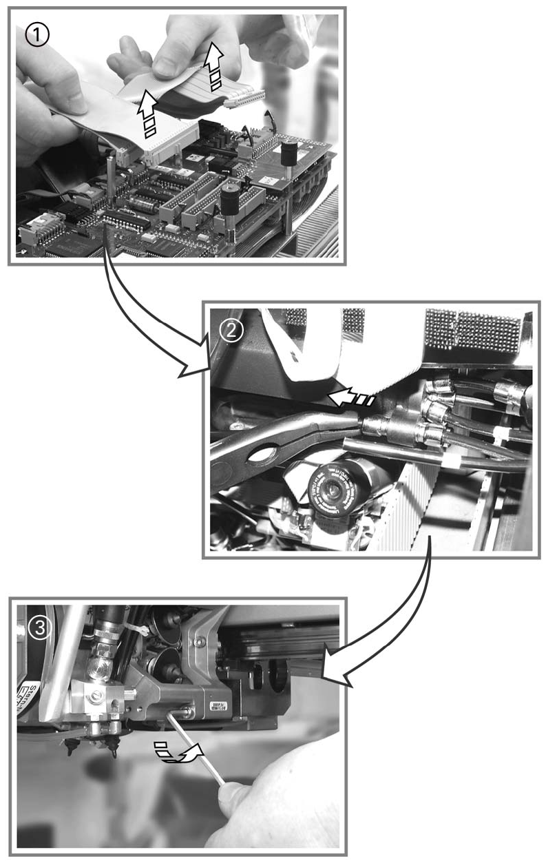
a Unplug the ribbon cables for the front part of head on the conversion board.
s Detach the compressed air hose.
To do this, use the pliers from the service box for the DLM 1 and DLM1-6 heads. 9
9
9
d Loosen the 3 (10.000er / 8000x head) or the 4 screws (DLM1 / DLM1-6) of the front part of
head (using a 3 mm Allen key) and remove it.
Hold the front part of head firmly as you remove the screws. 9
Look out for the white plastic distributor plate and the distributor. 9
9
Turn the star half a revolution to avoid damaging the valve plunger drive with the valve plunger.9
9
: Place the front part of the head on a soft ESD surface (with the valve plunger side underneath)
or place it on a suitable head stand.
: Remove the sleeves and place them in the containers provided.