Sonic Buzzer für D4.pdf - 第30页
2 Assembly instructi ons SOKO Sonic Buzzer SIPLACE D4 SOKO 10/2007 Edition 30 2.7 Circuit diagrams 2.7.1 Control unit 2 2 2 2 2 2 2 2 2 2 2 2 2 2 2 2 2 2 2 2 Wire colour Input/Output Function T erminal designation Pink I…
SOKO 2 Assembly instructions SOKO Sonic Buzzer SIPLACE D4
10/2007 Edition
29
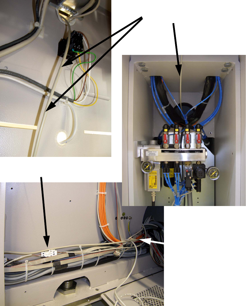
: Run the 2-wire cable, like shown on the following pictures, through the machine base to loca-
tion 4 and connect the plugs X1.
2
2
2
: Close all covers.
: Switch on the placement machine and test the function.
Running of the cable
Plug X1
Running of the cable

2 Assembly instructions SOKO Sonic Buzzer SIPLACE D4 SOKO
10/2007 Edition
30
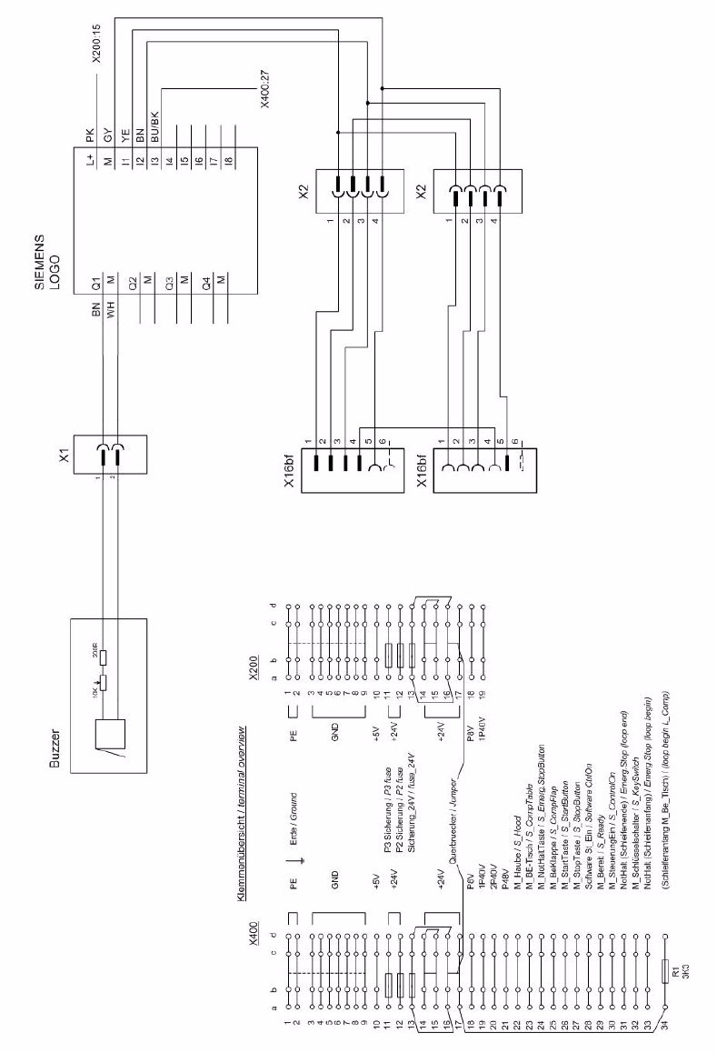
2.7 Circuit diagrams
2.7.1 Control unit
2
2
2
2
2
2
2
2
2
2
2
2
2
2
2
2
2
2
2
2
Wire colour Input/Output Function Terminal designation
Pink
Input +24V P
Grey
Input Ground (0V) M
Yellow
Input Signal light right I1
Brown
Input Signal light left I2
Blue/Black
Input Stop or reset I3
Brown
Output 24V Q1
White
Output Ground (0V) M
SOKO 2 Assembly instructions SOKO Sonic Buzzer SIPLACE D4
10/2007 Edition
31
2.7.2 SIPLACE D4
2
Fig. 2.12 - 1 Circuir diagram SIPLACE D4 (item no: 03063623-xx)