ASM-SX-V3-设备性能参数-DMS - 第14页
14 Placement heads SIPLACE SpeedStar (C&P20 P2) SIPLACE SpeedStar (C&P20 P2) With co mponent ca mera type 48 Component range a a) Please note that the placeable component range is also affect ed by the pad geomet…
13
Placement heads
General
Head modularity
The SIPLACE placement
machines are distinguished
by maximum flexibility in the
production process. This
flexibility is in part due to the
head modularity of the place-
ment machines, which allows
different placement head
variants to be configured to
suit the production require-
ments.
The SIPLACE SpeedStar
and the SIPLACE MultiStar
operate according to the
Collect&Place principle i.e.
one cycle includes pickup or
"collection" of 20 or 12 com-
ponents, their optical center-
ing on the board and their
rotation into the required
placement angle and posi-
tion. They are then placed
gently and accurately onto
the PCB. This principle is
particularly suitable for high-
speed placement of standard
components.
The SIPLACE MultiStar also
functions according to the
Pick&Place principle. Two
components are picked up
by the SIPLACE MultiStar,
optically centered on the way
to the placement position
and rotated into the required
placement angle. This princi-
ple is particularly suitable for
fast and precise placement
of large components.
The SIPLACE MultiStar uses
both the Collect&Place and
the Pick&Place principle.
Mixed Mode allows com-
bined use of these two
modes, which were previ-
ously separated from one
another, in one placement
cycle.
Pick&Place mode (Twin
Head)
The high-precision SIPLACE
TwinStar functions according
to the Pick&Place principle.
Two components are picked
up by the SIPLACE Twin-
Star, optically centered on
the way to the placement
position and rotated into the
required placement angle.
This principle is particularly
suitable for fast and precise
placement of special compo-
nents, such as those
required for grippers etc.
Control and self-learning
functions
The reliability of the
SIPLACE placement heads
can be enhanced even fur-
ther with various checking
and self-learning functions.
• Component sensor
Checks the presence of
the components on the
nozzle before the pickup
and placement process
• Digital camera
Checks the position of
each component on the
nozzle. This check is per-
formed in a single step,
with no extra time involved
but with optimum scan-
ning of each individual
component.
• Force sensor
Monitors the prescribed
component set-down
force.
The sensor stop proce-
dure enables compensa-
tion of height differences
during pickup and PCB
warpage during place-
ment.
• Vacuum sensor
Checks whether the com-
ponent was correctly
picked up or placed.
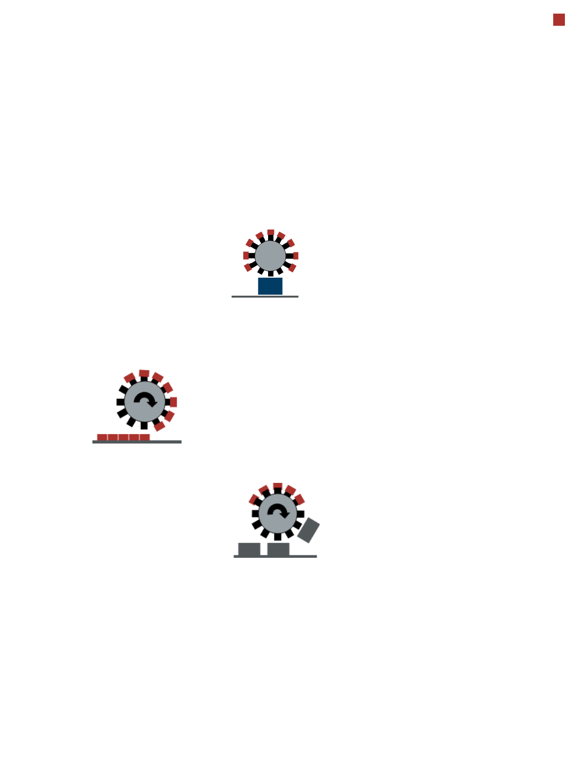
Collect&Place mode
Pick&Place mode
(SIPLACE MultiStar)
Mixed mode
14
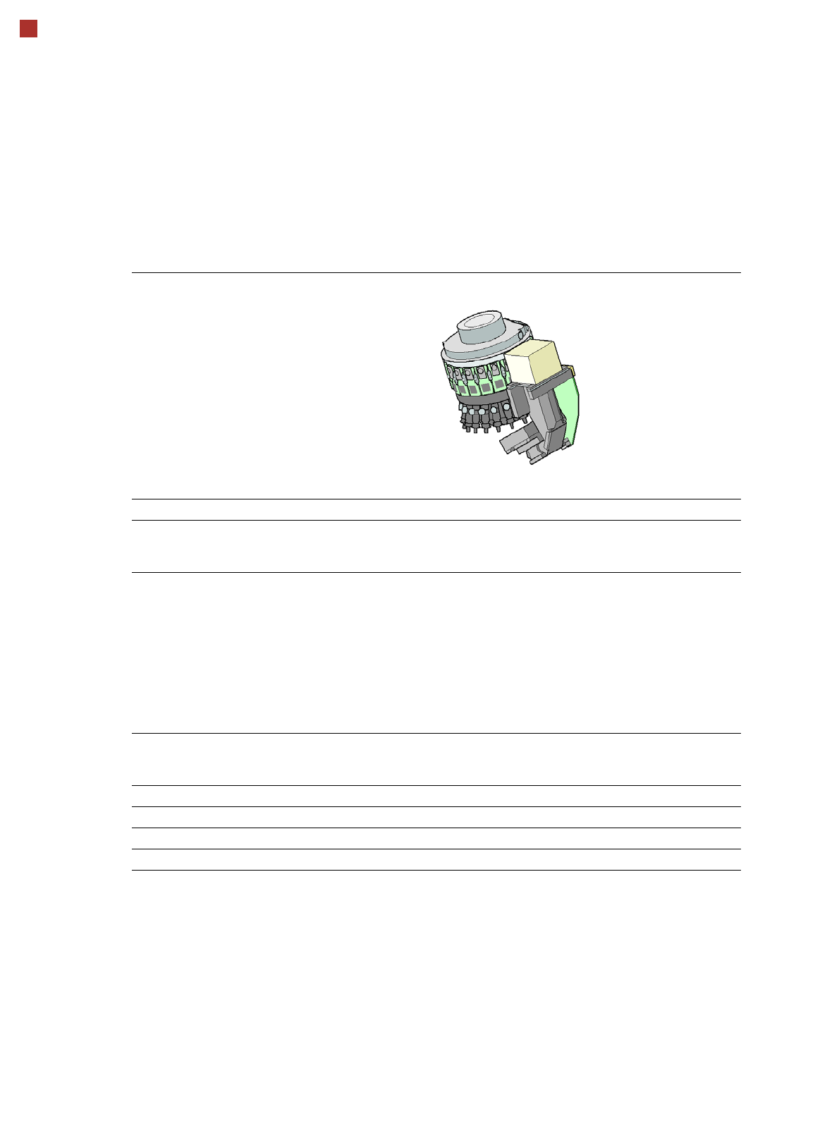
Placement heads
SIPLACE SpeedStar (C&P20 P2)
SIPLACE SpeedStar (C&P20 P2)
With component camera type 48
Component range
a
a) Please note that the placeable component range is also affected by the pad geometry, the customer-specific
standards, the component packaging tolerances and the component tolerances.
0.12 mm x 0.12 mm (0201 metric) to
2220, Melf, SOT, SOD, Bare-Die,
Flip-Chip
Component spec.
Max. height
Min. lead pitch
Min. lead width
Min. ball pitch
Min. ball diameter
Min. dimensions
Max. dimensions
Max. weight
4 mm
70 µm
30 µm
100 µm
50 µm
0.12 mm x 0.12 mm
8.2 mm x 8.2 mm
1 g
Set-down force 1.3 N ± 0.5 N (default value)
0.5 N - 4.5 N
Touchless Placement
Nozzle types 60xx
X/Y accuracy
b
b) The accuracy values fulfill the conditions in the SIPLACE scope of supply and services.
± 34 µm/3σ
Angular accuracy ± 0.5° / 3σ
Illumination levels 5
15
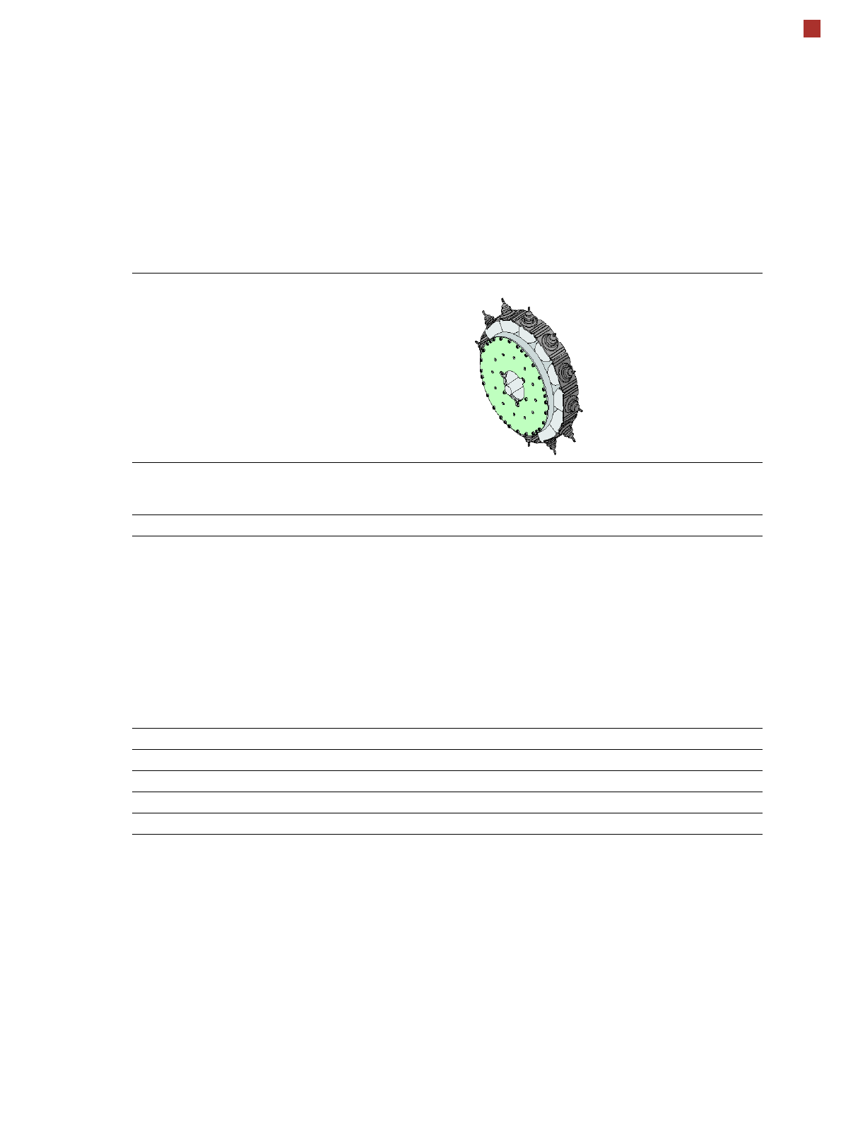
Placement heads
SIPLACE MultiStar (CPP)
SIPLACE MultiStar (CPP)
With component camera
type 30
With component camera
type 45
With component camera
type 33
(stationary camera)
Component range
a
a) Please note that the placeable component range is also affected by the pad geometry, the customer-specific stan-
dards, the component packaging tolerances and the component tolerances.
01005 to 27 mm x 27 mm 01005 to 15 mm x 15 mm 0402 to 50 mm x 40 mm
b
b) A diagonal of 69 mm is possible during multiple measurements (e.g. 64 mm x 10 mm).
Component spec.
Max height
c
Max. height
d
Min. lead pitch
Min. lead width
Min. ball pitch
Min. ball diameter
Min. dimensions
Max. dimensions
Max. weight
c) CPP head: in low installation position (stationary component camera not possible).
d) CPP head: In high installation position
6.0 mm
8.5 mm
250 µm
100 µm
e
/ 200 µm
f
250 µm
e
/ 350 µm
f
140 µm
e
/ 200 µm
f
0.4 mm x 0.2 mm
27 mm x 27 mm
4 g
g
e) For components < 18 mm x 18 mm.
f) For components ≥ 18 mm x18 mm.
g) 20 g in "Pick&Place" mode
6.0 mm
8.5 mm
250 µm / 120 µm
h
50 µm
140 µm
70 µm
0.11 mm x 0.11 mm
15 mm x 15 mm
4 g
g
h) Only possible for components which are within the focal range of the camera of ± 1.3 mm.
11.5 mm / 15.5 mm
i
300 µm
150 µm
350 µm
200 µm
1.0 mm x 0.5 mm
50 mm x 40 mm
8 g
g
i) 15.5 mm only in top assembly position, with OSC package and restrictions.
See also OSC package on page 41.
Set-down force 1.0 - 15 N
j
j) 10 N standard, with OSC package 15 N.
Nozzle types 20xx, 28xx
X/Y accuracy
k
k) The accuracy values fulfill the conditions in the SIPLACE scope of supply and services.
± 38 µm/3σ ± 38 µm/3σ ± 30 µm/3σ
Angular accuracy ± 0.20° / 3σ
l
, ± 0.38° / 3σ
m
l) Component dimensions between 6 mm x 6 mm and 27 mm x 27 mm.
m) Component dimensions smaller than 6 mm x 6 mm.
± 0.38° / 3σ ± 0.12° / 3σ
Illumination levels 5 5 6