ASM-SX-V3-设备性能参数-DMS - 第16页
16 Placement heads SIPLACE TwinStar (TH) SIPLACE TwinStar (TH) With component camera type 33 (fine pitc h camera) With component c amera type 25 (flip chip camera) Component range a a) Please note that the placeable comp…
15
Placement heads
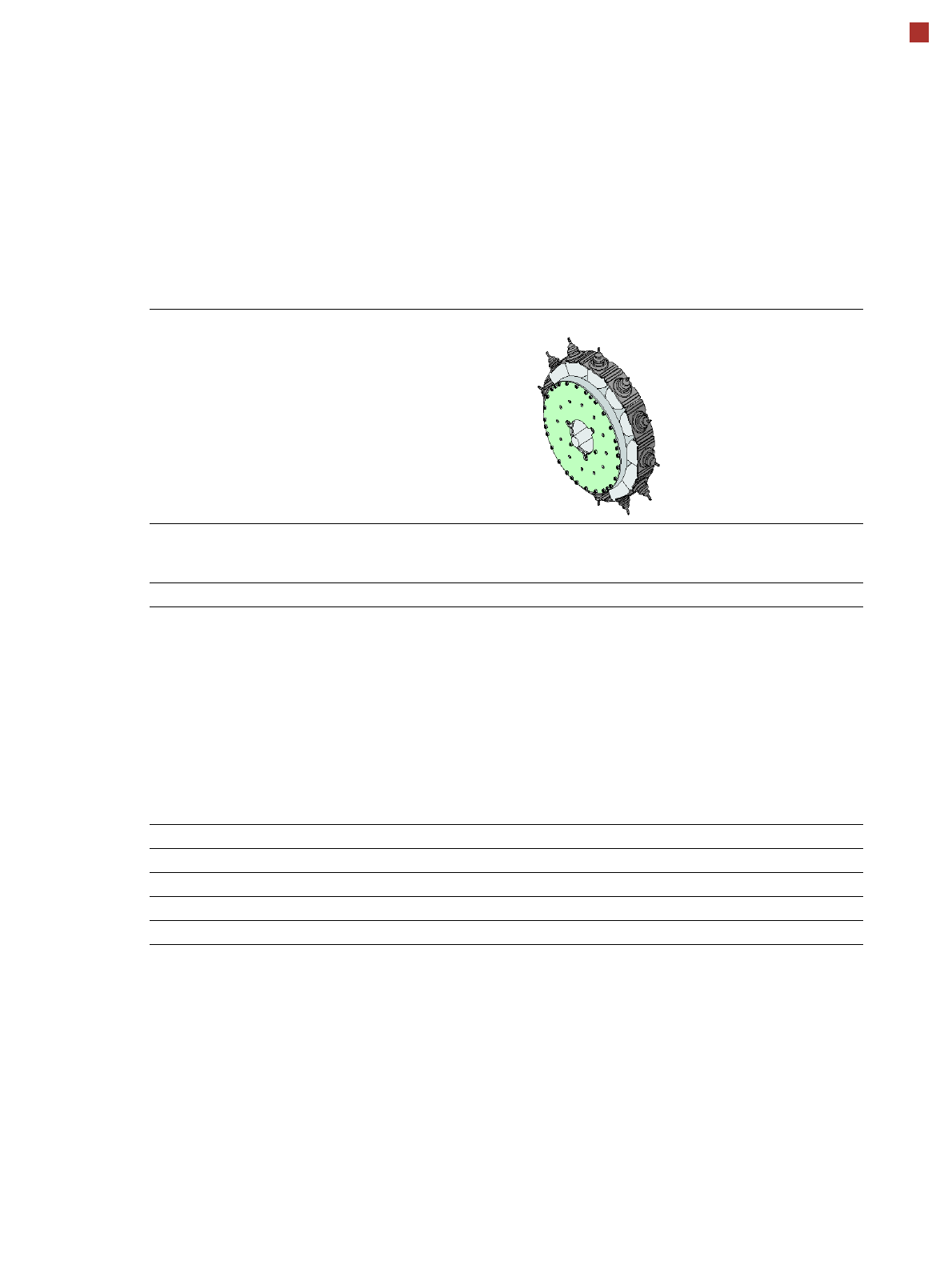
SIPLACE MultiStar (CPP)
SIPLACE MultiStar (CPP)
With component camera
type 30
With component camera
type 45
With component camera
type 33
(stationary camera)
Component range
a
a) Please note that the placeable component range is also affected by the pad geometry, the customer-specific stan-
dards, the component packaging tolerances and the component tolerances.
01005 to 27 mm x 27 mm 01005 to 15 mm x 15 mm 0402 to 50 mm x 40 mm
b
b) A diagonal of 69 mm is possible during multiple measurements (e.g. 64 mm x 10 mm).
Component spec.
Max height
c
Max. height
d
Min. lead pitch
Min. lead width
Min. ball pitch
Min. ball diameter
Min. dimensions
Max. dimensions
Max. weight
c) CPP head: in low installation position (stationary component camera not possible).
d) CPP head: In high installation position
6.0 mm
8.5 mm
250 µm
100 µm
e
/ 200 µm
f
250 µm
e
/ 350 µm
f
140 µm
e
/ 200 µm
f
0.4 mm x 0.2 mm
27 mm x 27 mm
4 g
g
e) For components < 18 mm x 18 mm.
f) For components ≥ 18 mm x18 mm.
g) 20 g in "Pick&Place" mode
6.0 mm
8.5 mm
250 µm / 120 µm
h
50 µm
140 µm
70 µm
0.11 mm x 0.11 mm
15 mm x 15 mm
4 g
g
h) Only possible for components which are within the focal range of the camera of ± 1.3 mm.
11.5 mm / 15.5 mm
i
300 µm
150 µm
350 µm
200 µm
1.0 mm x 0.5 mm
50 mm x 40 mm
8 g
g
i) 15.5 mm only in top assembly position, with OSC package and restrictions.
See also OSC package on page 41.
Set-down force 1.0 - 15 N
j
j) 10 N standard, with OSC package 15 N.
Nozzle types 20xx, 28xx
X/Y accuracy
k
k) The accuracy values fulfill the conditions in the SIPLACE scope of supply and services.
± 38 µm/3σ ± 38 µm/3σ ± 30 µm/3σ
Angular accuracy ± 0.20° / 3σ
l
, ± 0.38° / 3σ
m
l) Component dimensions between 6 mm x 6 mm and 27 mm x 27 mm.
m) Component dimensions smaller than 6 mm x 6 mm.
± 0.38° / 3σ ± 0.12° / 3σ
Illumination levels 5 5 6
16
Placement heads
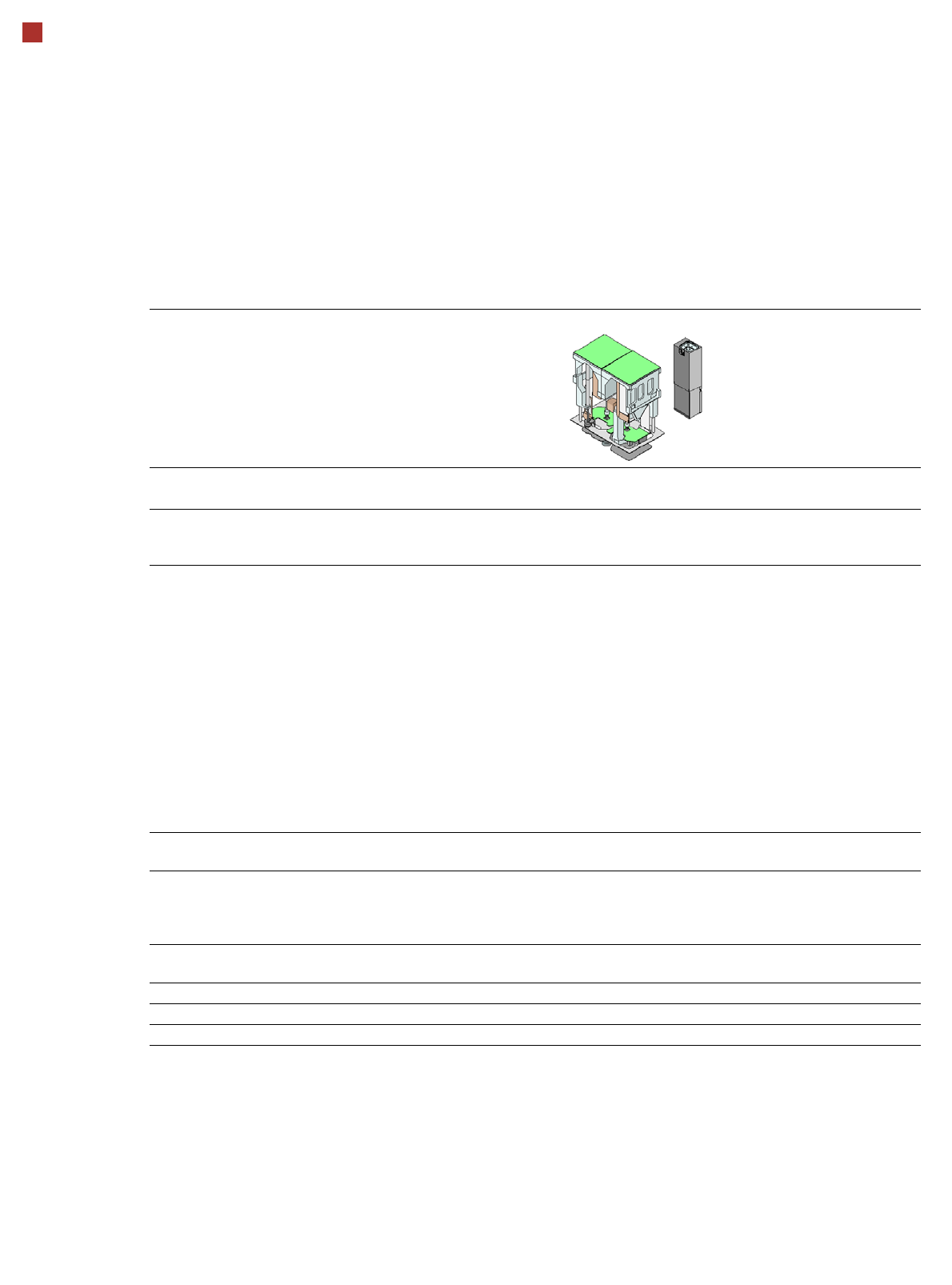
SIPLACE TwinStar (TH)
SIPLACE TwinStar (TH)
With component camera type 33
(fine pitch camera)
With component camera type 25
(flip chip camera)
Component range
a
a) Please note that the placeable component range is also affected by the pad geometry, the customer-specific standards, the
component packaging tolerances and the component tolerances.
0402 to SO, PLCC, QFP, BGA, special
components, bare dies, flip-chips
0201 to SO, PLCC, QFP, sockets,
plugs, BGA, special components, bare
dies, flip-chips, shields
Component specs
Max. height
Min. lead pitch
Min. lead width
Min. ball pitch
Min. ball diameter
Min. dimensions
Max. dimensions
Max. weight
b
b) Component plus nozzle or gripper.
25 mm / 40 mm
c
300 µm
150 µm
350 µm
200 µm
1.0mm x 0.5mm
55 mm x 45 mm (single measurement)
Up to
200 mm x 110 mm (multiple measurement)
d
100 g to 300 g
e
c) Maximum height up to 50 mm available on request with SIPLACE Very High Force Twin Star (VHF TH) and OSC package.
d) Further restrictions will apply, according to the component dimensions and the component supply. These will be automati-
cally taken into account by SIPLACE Pro.
e) Up to 100 g is standard. Over 100 g available with reduced acceleration. From 160 g upwards only available with the SI-
PLACE Very High Force Twin Star (VHF TH). For components of up to 300 g, use the function at the station for measuring
and determining the inertia of components and nozzles. Recommendation: The function for measuring the moment of in-
ertia for components with a weight of 50 g or more.
25 mm / 40 mm
c
250 µm
100 µm
140 µm
80 µm
0.6 mm x 0.3 mm
16 mm x 16 mm (single measurement)
Up to
55 mm x 55 mm (multiple measure-
ment)
d
100 g to 300 g
e
Set-down force 1.0 N - 30 N
f
2.0 N -100 N
g
f) 15 N standard, with OSC package 30 N.
g) 70 N standard with SIPLACE Very High Force Twin Star (VHF TH), with OSC package 100 N.
Nozzle types
h
h) Over 300 different nozzles and 100 gripper types are available, with an extensive nozzle database available online.
5xx (standard)
20xx/28xx + adapter
9xx + adapter
Gripper
Nozzle spacing for P&P
heads
70.8 mm
X/Y accuracy
i
i) The accuracy values fulfill the conditions in the SIPLACE scope of supply and services.
± 26 µm/3σ ± 22 µm/3σ
Angular accuracy ± 0.05° / 3σ ± 0.05° / 3σ
Illumination levels 6 6
17
Placement heads
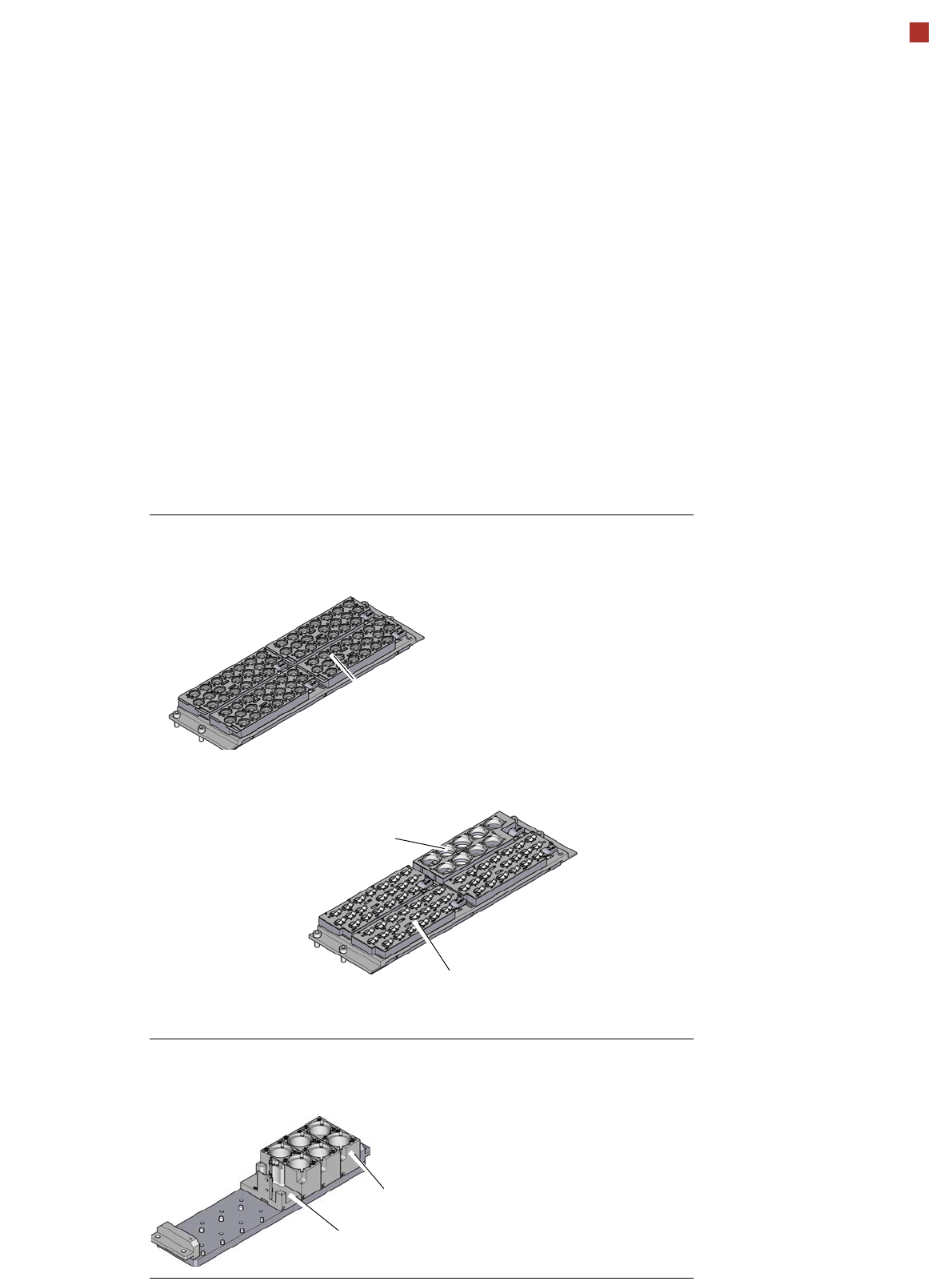
Nozzle changer
Nozzle changer for the SIPLACE SpeedStar (C&P20 P2)
Nozzle changer for the SIPLACE MultiStar CPP
Nozzle changer for the SIPLACE TwinStar (TH)
Magazine for 20 nozzles
of type 60xx
Magazine for 9 nozzles of
type 28xx
Magazine for 20 nozzles of type 20xx
Magazine for two standard nozzles
Magazine for one special nozzle, gripper
Description
Nozzle changers increase the flexibility of the placement heads when it comes to processing
different components. The nozzle configuration can be rapidly adjusted to changing place-
ment jobs. Precisely defined positions and perfect nozzle seat in the garage ensure minimum
radial eccentricity on the placement head.
The nozzle changers feature a monitoring circuit. This checks whether the nozzle magazines
are seated correctly on the mount. In addition, the nozzle changers recognize whether the
magazines are for 40xx/60xx, 20xx or 28xx nozzles by the code.