ASM-SX-V3-设备性能参数-DMS - 第24页
24 PCB warpage PCB warpage during placement To avoid impairing the placement quality and speed, we recommend u sing a PCB support e.g. Smart Pin Support so that the PCB warpag e downwards does not exceed 0.5 mm. PCB warp…
23
PCB warpage
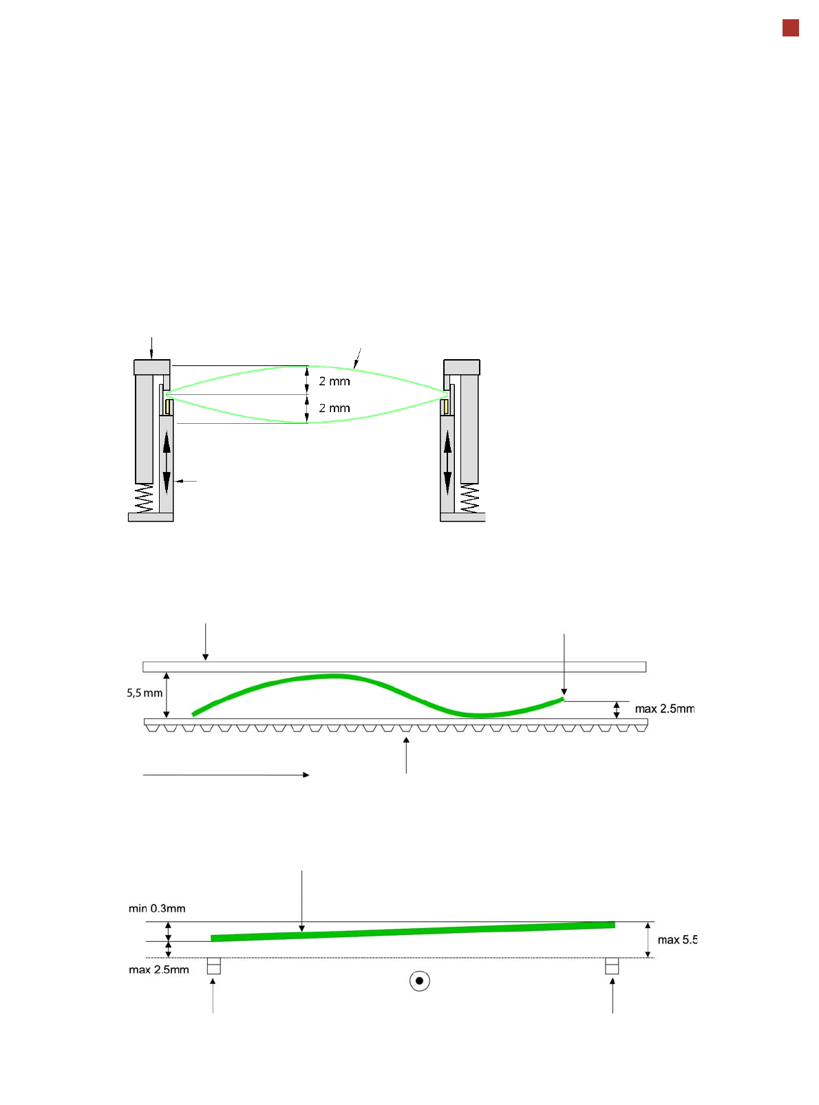
PCB warpage across the direction of travel
max. 1 % of the PCB diagonal, but not
exceeding 2 mm
PCB warpage on the conveyor
Fixed clamped edge
Movable clamping device
PCB
Fixed clamped edge
Conveyor belt
PCB transport direction
Front board edge
Front board edge
PCB warpage in direction of travel + PCB thickness < 5.5
mm
Bending up of front board edge max. 2.5 mm
Left conveyor belt
Right conveyor belt
PCB transport direction
24
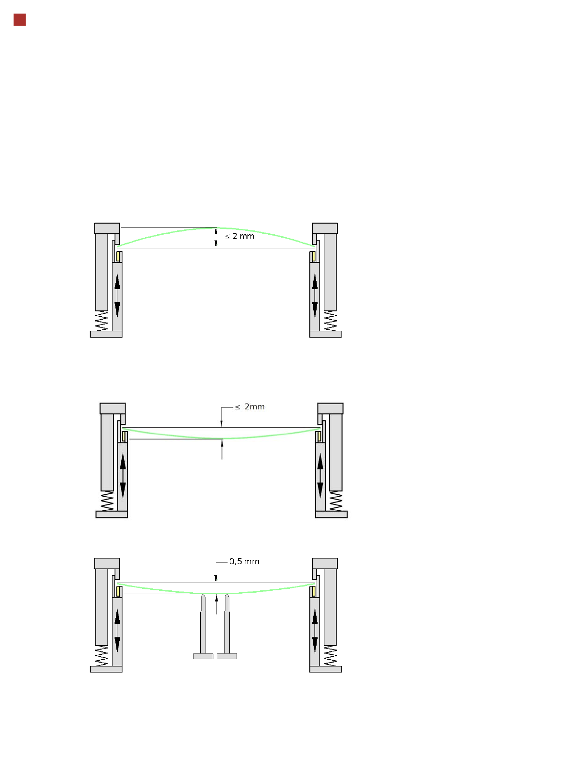
PCB warpage
PCB warpage during placement
To avoid impairing the placement quality and
speed, we recommend using a PCB support e.g.
Smart Pin Support so that the PCB warpage
downwards does not exceed 0.5 mm.
PCB warpage up, max. 2 mm
PCB support
PCB warpage down, max. 2 mm
Changes in the surface position are automatically applied by the functions for learning the height.
25
Virtual Inkspot Handler (VIH)
The virtual inkspot handler
(VIH) allows you to scan in
inkspots from an external
system.
This option can be used for
external systems to define
which panels are to be
produced and which to be
omitted. A panel is a specific
part of a printed circuit
board. This concept is much
more flexible than the
physical inkspot concept.
It can be integrated into the
ongoing production process,
if external systems
individually decide whether
each panel it is in a good or
bad state and whether
additional processing steps
are to be omitted or not.
The boards are typically
measured by the external
system and the information
about which panels are good
or bad is then available.
The use of this information
via VIH offers the benefit that
no physical inkspots need to
be read by the PCB camera.
This improves performance,
particularly for boards with a
large number of panels.
This option can also be used
if the panels do not have
room for a physical inkspot.
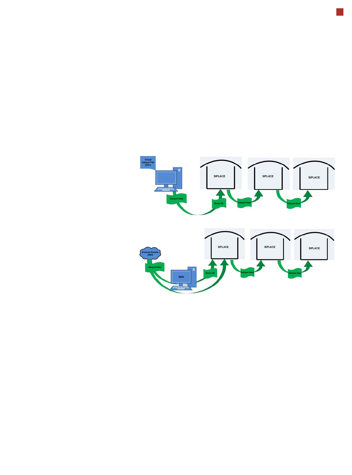
Workflow VIH with XML file
Workflow VIH with MES and BoardGateKeeper (BGK)
Process Data Interfaces (PDI)
The process data interface (PDI), which can be addressed via
the OIB interface, enables you to access not only the trace-
ability data of the components placed but also various process
parameters for the component placement. The PDI makes
over 40 process attributes per placement position available,
such as:
• Pickup (actual pick position, pickup location ID)
• Dipping (result, timestamp)
• Vision measuring (result plus camera ID)
• Placement (actual place position, ref. desig., vacuum val-
ues)
The data packages contain the data for each board and stop-
per position.
Each individual data package contains a maximum of 200
placement positions.