ASM-SX-V3-设备性能参数-DMS - 第26页
26 Smart Pin Support Smart Pin Support The Smart Pin Support option automatically places support pins o n the lifting table. A gripper u nit is used to take the support pins out of the smart pin magazine a n d place them…
25
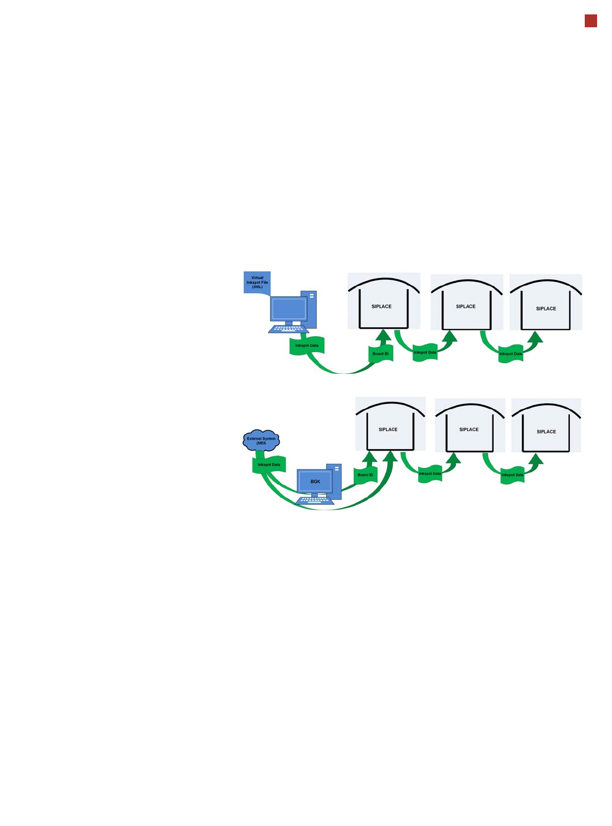
Virtual Inkspot Handler (VIH)
The virtual inkspot handler
(VIH) allows you to scan in
inkspots from an external
system.
This option can be used for
external systems to define
which panels are to be
produced and which to be
omitted. A panel is a specific
part of a printed circuit
board. This concept is much
more flexible than the
physical inkspot concept.
It can be integrated into the
ongoing production process,
if external systems
individually decide whether
each panel it is in a good or
bad state and whether
additional processing steps
are to be omitted or not.
The boards are typically
measured by the external
system and the information
about which panels are good
or bad is then available.
The use of this information
via VIH offers the benefit that
no physical inkspots need to
be read by the PCB camera.
This improves performance,
particularly for boards with a
large number of panels.
This option can also be used
if the panels do not have
room for a physical inkspot.
Workflow VIH with XML file
Workflow VIH with MES and BoardGateKeeper (BGK)
Process Data Interfaces (PDI)
The process data interface (PDI), which can be addressed via
the OIB interface, enables you to access not only the trace-
ability data of the components placed but also various process
parameters for the component placement. The PDI makes
over 40 process attributes per placement position available,
such as:
• Pickup (actual pick position, pickup location ID)
• Dipping (result, timestamp)
• Vision measuring (result plus camera ID)
• Placement (actual place position, ref. desig., vacuum val-
ues)
The data packages contain the data for each board and stop-
per position.
Each individual data package contains a maximum of 200
placement positions.
26
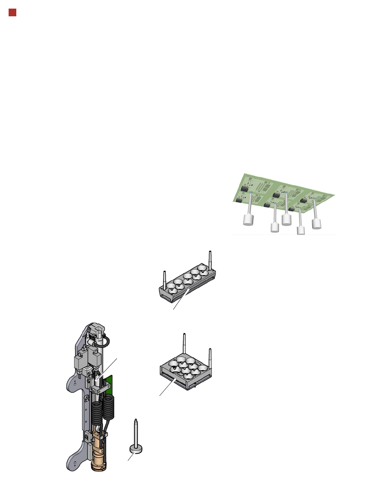
Smart Pin Support
Smart Pin Support
The Smart Pin Support
option automatically places
support pins on the lifting
table. A gripper unit is used
to take the support pins out of
the smart pin magazine and
place them in the predefined
positions.
Before a Smart Support pin
is placed, the position is
cleaned of any contaminants
with a gentle blast of air. In
addition, the correct position-
ing of the support pin is
checked after its placement,
with the PCB camera.
Smart pin magazine
There are two different mag-
azines available for auto-
matic changeover of max. 10
support pins in the various
machine configurations.
These magazines are fixed
to a magazine holder and are
fitted to the COT insert.
Programming
The positions of the support
pins in the machine can be
defined for each board side,
in the SIPLACE Pro Board
Editor.
A 3D image of the board and
the support pins allows you
to recognize and prevent any
collision risks between the
support pin and the compo-
nents, even for stepped
transportation of boards with
excess length.
Gripper unit
Support pin
Magazine L 10
Magazine Q 10
27
Component feeding
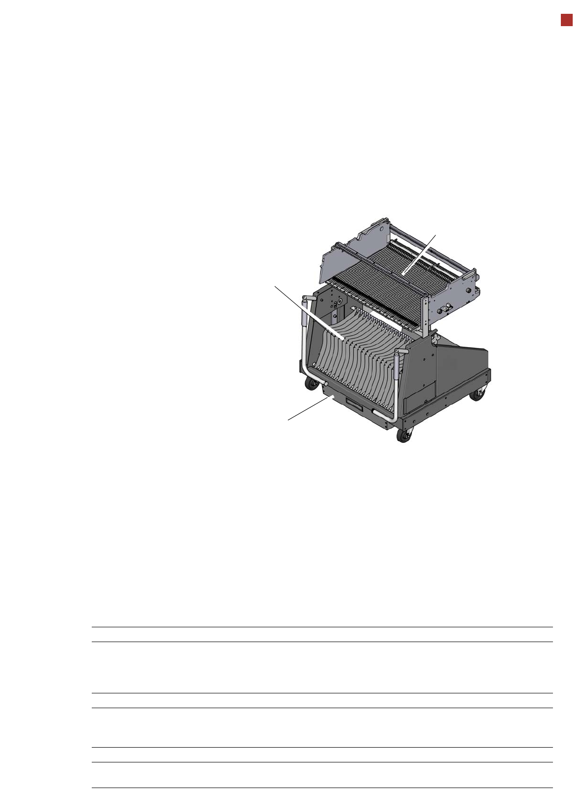
Component trolley
Component trolley
SIPLACE SX
The SIPLACE SX compo-
nent trolleys are independent
and easily maneuverable
modules. The SIPLACE SX
machines can accommodate
two component trolleys, each
with 60 tracks. If a WPC5/
WPC6 is set up at one of the
locations, the other location
can accommodate a compo-
nent trolley with 30 tracks.
The tape reels are taken up
into the tape container of the
component trolley. A cutting
device on the machine auto-
matically cuts up the used
tape material. The compo-
nent trolleys can be set up
directly on the machine or at
an external setup area with
feeder modules. The benefits
of offline setup are that the
configurations can be pre-
pared without stopping the
line.
This allows the setup change
to be realized very quickly,
using the changeover table
principle, to rapidly change
the component trolleys.
The SIPLACE SX compo-
nent trolleys also support fast
setting up and tearing down
of feeder modules even
during the placement pro-
cess. Tapes can be spliced
without stopping the
machine.
For safety reasons, unoccu-
pied locations are fitted with
so-called dummy feeder
modules.
Component trolley SIPLACE SX
Tape container
Waste container for remaining
empty tape
Changeover table
Component supply Tracks occupied
2 component trolleys with tape reel holder and integral waste
bins
When using a Waffle Pack Changer:
120 locations for feeder modules,
each 8 mm.
90 locations for feeder modules,
each 8 mm.
Tape reel diameter
Standard
Maximum
To 432 mm (17")
483 mm (19")
Component trolley changeover time < 1 minute
Feeder module types Tape feeder modules, reject conveyor, stick
magazine and label presenter.