00196624-04_Service Manual WPC5_6_EN_01-2019.pdf - 第119页
Service Manua l WPC5 / WPC6 Page 4-119 4.1.4 Calibrating the Limit Switch The p lus an d min us pos ition o f the limit switc hes nee d to b e calibr ated. ➢ Remo ve all waffle -pack tray c arriers (WPTC) from the WPC …
Service Manual WPC5 / WPC6
Page 4-118
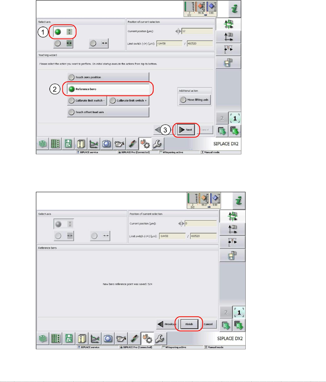
4.1.3 Reference Proximity Switch (Bero)
➢ Remove all waffle-pack tray carriers (WPTC) from the WPC.
➢ Select the lifting axis (1).
➢ Select the function
Reference bero
(2).
➢ Select
Next
(3).
➢ Confirm the new reference point proximity switch with
Finish
.
Service Manual WPC5 / WPC6
Page 4-119
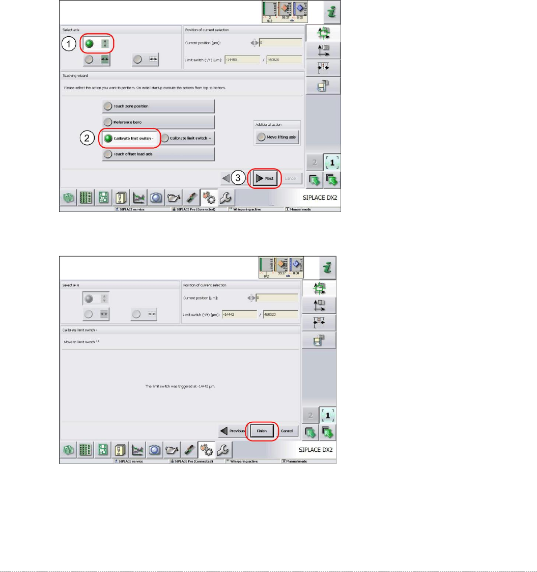
4.1.4 Calibrating the Limit Switch
The plus and minus position of the limit switches need to be calibrated.
➢ Remove all waffle-pack tray carriers (WPTC) from the WPC.
➢ Select the lifting axis (1).
➢ Select the function
Calibrate limit switch
- (2).
➢ Select
Next
(3).
Calibrating the limit switch -
➢ Confirm the new position at which the limit switch triggers with
Finish
.
Calibrating the limit switch +
➢ Select the lifting axis (1).
➢ Select the function
Calibrate limit switch +
and continue with the same procedure as that
used for calibrating the limit switch.
Service Manual WPC5 / WPC6
Page 4-120
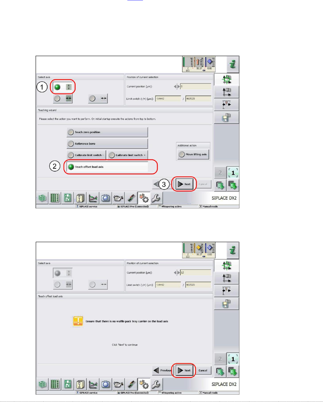
4.1.5 Teaching the Load Axis Offset Point
You only need to teach the offset point if you have changed the zero point position (see "4.1.2
Teaching the Zero Point Position" [
➙
4-115]).
➢ Remove all waffle-pack tray carriers (WPTC) from the WPC.
➢ Select the lifting axis (1).
➢ Select the function
Teach offset load axis
(2).
➢ Select
Next
(3).
➢ Follow the instruction shown and continue with
Next
.