00196624-04_Service Manual WPC5_6_EN_01-2019.pdf - 第42页
Service Manua l WPC5 / WPC6 Page 3- 42 3.5.5 Replace the Driver Assembly Spare Part • Driver assem bly [03053436- xx] Preparations ➢ Move the tower into the refill position. ➢ Remove all waffle p ack tray carriers (WP …

Service Manual WPC5 / WPC6
Page 3-41
➢ Unplug the connector X2 (2) belonging to the cable for the lifting magnet which closes the
safety flap and connector X7 (1) from the circuit board.
➢ Loosen the screws fastening the magnet holder (3 and 4) and lift out the holder with the
magnets.
➢ Dismantle the magnets to be replaced from the holder. To do this, loosen the relevant circlip
(at 7 for lifting magnet 1 or 8 for lifting magnet 2) and pull out the axis bolt. Check whether
there are any washers fitted and make a note of their positions if there are any..
Installation
➢ Set the same lift as used for the dismantled magnets.
➢ Insert the new lifting magnets with the axis bolts into the mount.
➢ Fix the axis bolt into place with the washers and the circlip.
➢ Fit the new lifting magnet by following the instructions for removal in reverse order.
NOTICE
Circlip
The circlip can be easily damaged. Take great care when removing it.
Service Manual WPC5 / WPC6
Page 3-42
3.5.5 Replace the Driver Assembly
Spare Part
• Driver assembly [03053436-xx]
Preparations
➢ Move the tower into the refill position.
➢ Remove all waffle pack tray carriers (WPTCs) from the tower.
➢ Move the tower downwards.
⇨ Check sensors and functions ⇨ Check sensors and functions of specific components ⇨ Location ⇨
⇨ Check functions for WPC ⇨ Move into transport position.
➢ Undock the WPC from the SIPLACE machine and move it to a suitable pos. for service work.
➢ Switch the WPC off at the main switch.
➢ Unplug from the power supply and secure the WPC to prevent unauthorized reactivation.
➢ Remove the cover from the non-stop module (see "3.5.1.1 Remove the Cover on the Load
Unit" [➙
3-32]).
➢ Remove the hand guard from the feed axis (see "3.5.1.2 Remove the Right Side Cover from
the WPC" [➙ 3-32]).
Removal / Installation
➢ Readjust the belt tension (see "3.5.6 [➙
3-43]).
➢ Continue with chapter "4.3 Ladeachse kalibrieren (nur WPC6)" [➙ 4-132].
See also...
@
3.5.3
Replace the Load Axis Drive Toothed Belt [03053795-xx] [➙ 3-37]
@
3.5.1.4
Loosen the Tension of the Load Axis Drive Belt [
➙
3-33]
Removal
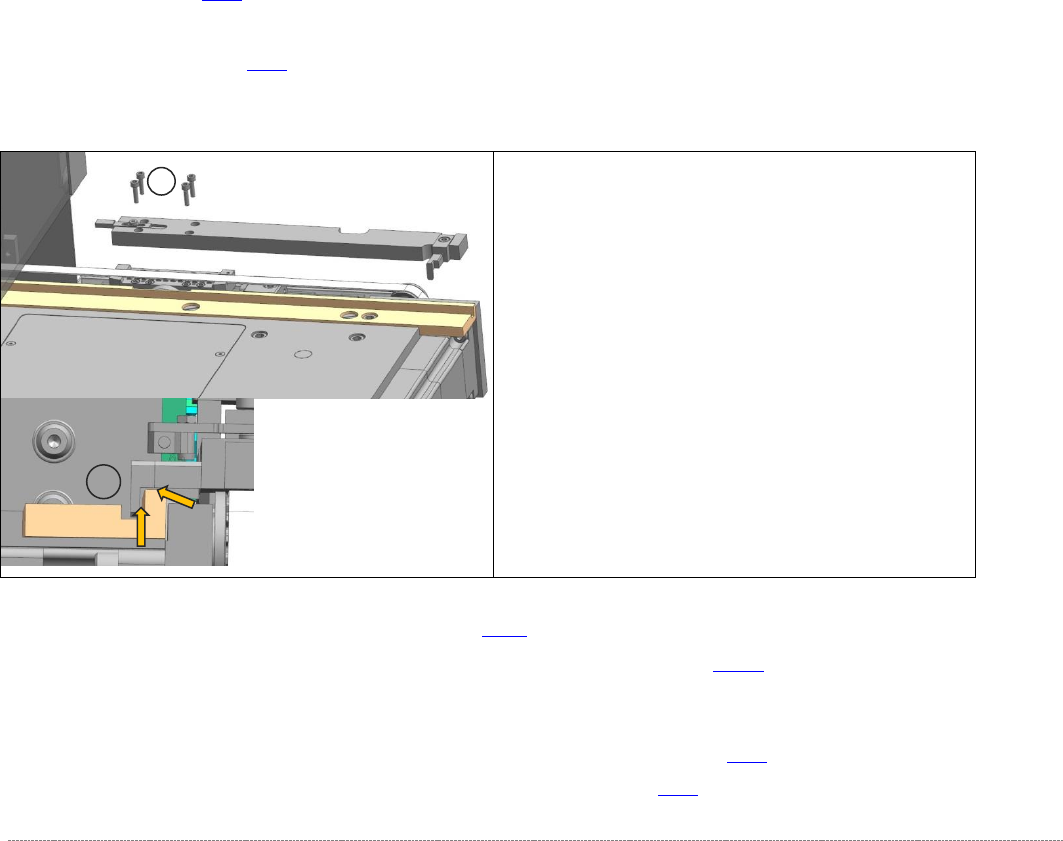
➢ Loosen the four screws (1) fastening the driver unit
and lift out the unit.
Installation
➢ Fit the new driver unit.
➢ Make sure that the driver (3) does not rub against
the slide bar. If necessary, loosen the fastening
screw and adjust the driver accordingly. Then
retighten the fastening screw.
1
3
Service Manual WPC5 / WPC6
Page 3-43
3.5.6 Setting the Load Axis Belt Tension
Tools Required
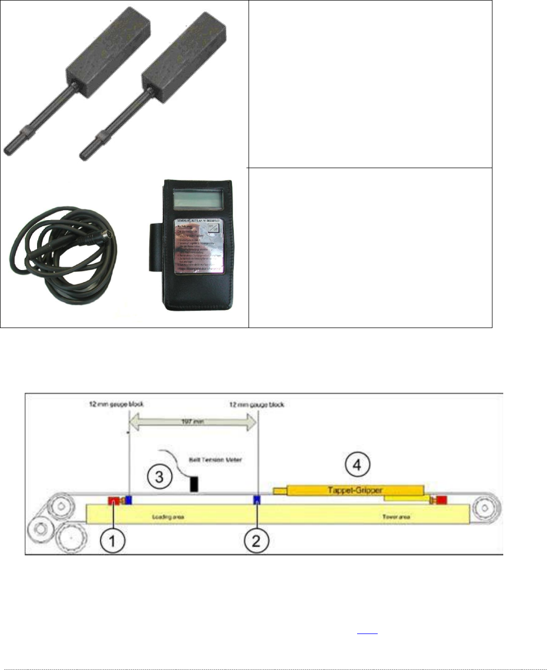
Measurement setup - measuring the belt tension for the load axis
➢ Push the two setting gauges (1 and 2) under the toothed belt, at a distance of 197 mm.
⇨ Belt tension setting value:
85 +-5Hz
➢ Tension the belt at the tensioning device with the deflection pulley (see (2) in "3.5.3
Replacing the Load Axis Drive Toothed Belt [03053795-xx]" [➙ 3-37]).
• Setting gauge small [03052363-02] 2x
• Belt tension measuring device [00326015-
xx] with instruction guide