00196624-04_Service Manual WPC5_6_EN_01-2019.pdf - 第47页
Service Manua l WPC5 / WPC6 Page 3- 47 3.6.3 Control Unit 3.6.3.1 Inst ructions f or W orking with Control Units CAUTION Observe the ESD regulati ons! W hen ha ndling control un it assemblies, observe th e ESD regulati…
Service Manual WPC5 / WPC6
Page 3-46
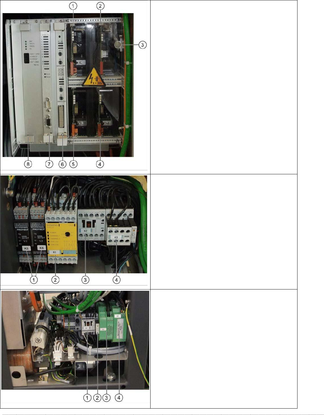
3.6.2 Overview
Front top
- overview of servo amplifier and cards
1. Servo amplifier for feed axis (3A)
2. Ballast Circuit
3. Braking resistor for lifting axis
4. Servo amplifier for load axis (WPC6 only)
5. Servo amplifier for lifting axis (10A)
6. Axis card KSP A364 analog
7.
Controller Board
8.
Supply board
From bottom
- overview of electrical unit
1. Protective door monitor and emergency STOP,
K5 and K6 (WPC6 only)
2. SSK K1
3. Contactor K 2
4. Contactor K 3
Back bottom
- overview of electrical unit
1. Contactor 3RT10 15-2BM42, K4
2. Suppression diode for contactors DC150-250V
on K4
3. Inrush current limitation board WPC
[03047752-xx] (WPC6 only)
4. Inrush current limitation board WPC NS
(WPC6 only)

Service Manual WPC5 / WPC6
Page 3-47
3.6.3 Control Unit
3.6.3.1 Instructions for Working with Control Units
CAUTION
Observe the ESD regulations!
When handling control unit assemblies, observe the ESD regulations for your own safety
and the safety of the machine:
➢ When removing or installing individual assemblies, always wear the ESD wristband, to prevent
damage to the electronics system.
➢
Also observe the ESD regulations specified in the SIPLACE SX1/SX2 user manual.
3.6.3.2 Replace the Power Supply Board
Spare Part
• WPC power supply board [03071546-xx]
Removal / Installation
➢ Wear the ESD wristband.
➢ Open the top and bottom locks and loosen the 4 screws fastening the front plate of the
power supply board.
➢ Carefully pull the power supply board (see "3.6.3 Control Unit" [➙
3-47]) out of the control
unit.
➢ Carefully insert the new power supply board.
➢ Make sure that the power supply board engages properly.
➢
Tighten the 4 screws fastening the front plate of the power supply board and lock the top
and bottom locks.
Settings
• No settings are required.
NOTICE
Check the power supply board voltages
The green LEDs on the power supply board only show whether voltage is present or not
(function monitoring). They do not show whether this voltage is correct.
Use a digital multimeter to measure the voltages at the respective pins on the front plate
of the power supply board.
Service Manual WPC5 / WPC6
Page 3-48
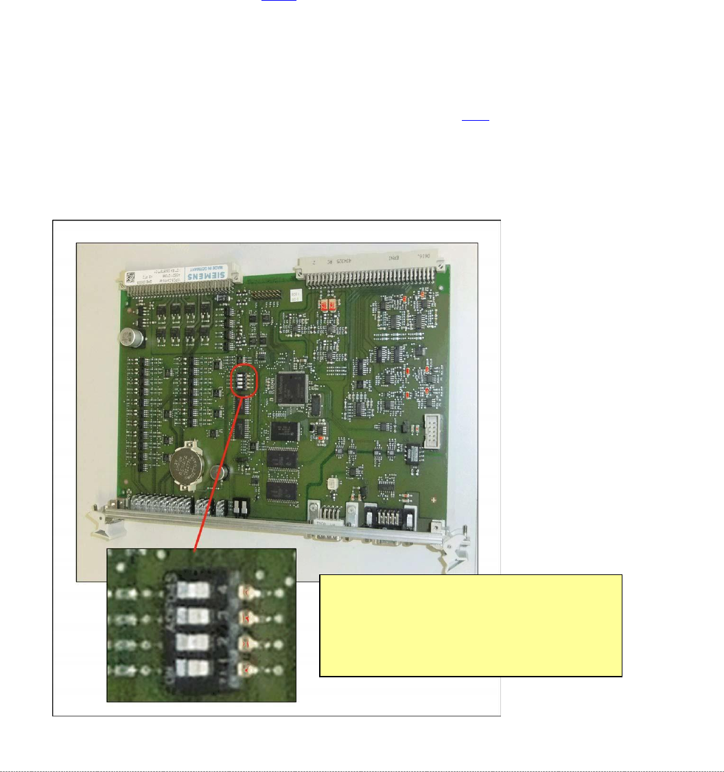
3.6.3.3 Replace the Controller Board
Spare Part
• WPC5 Controller Board [03057377-xx]
Removal / Installation
➢ Make a backup copy of the machine data, if this is still possible (*.xml). See "4.5 Storing and
Restoring Machine Data" [➙
4-140].
➢ Wear the ESD wristband.
➢ Unplug the CAN bus cable from the front of the controller board.
➢ Loosen the 2 screws fastening the front plate of the controller board.
➢ Unlock the top and bottom locks.
➢ Carefully pull the controller board (see "3.6.3 Control Unit" [➙
3-47]) out of the control unit.
➢
Make sure that the jumper on the new controller board is set identically to that on the
controller board to be replaced.
Position of the Jumper on the Controller
Board
•
Settings for
WPC5:
Jumper 1 to 3 Off, Jumper 4 On
•
Settings for
WPC6:
Jumper 1 and 3 Off, Jumper 2 and 4 On