00196624-04_Service Manual WPC5_6_EN_01-2019.pdf - 第53页
Service Manua l WPC5 / WPC6 Page 3- 53 3.6.3.7 Repla ce the B allast C ircuit Spare Part • Ballast circuit LZ S200/1000 [00344207 - xx] Removal / Install ation ➢ Wear the ESD wristband . ➢ Loosen the 4 screws faste nin…
Service Manual WPC5 / WPC6
Page 3-52
3.6.3.6 Replace the Servo Amplifier for the Non-Stop Module
Spare Part
• Servo amplifier TBS 200/3Z1 [03048005-xx] for Non-Stop-Module
Removal / Installation
➢ Move the tower into the refill position and switch the WPC off.
➢ Wear the ESD wristband.
➢ Remove the second side cover from the control unit side.
➢ Loosen the 4 screws fastening the plexiglass cover and remove this.
Settings
• No settings are required.
See also...
@
3.6.3
Control Unit [➙ 3-47]
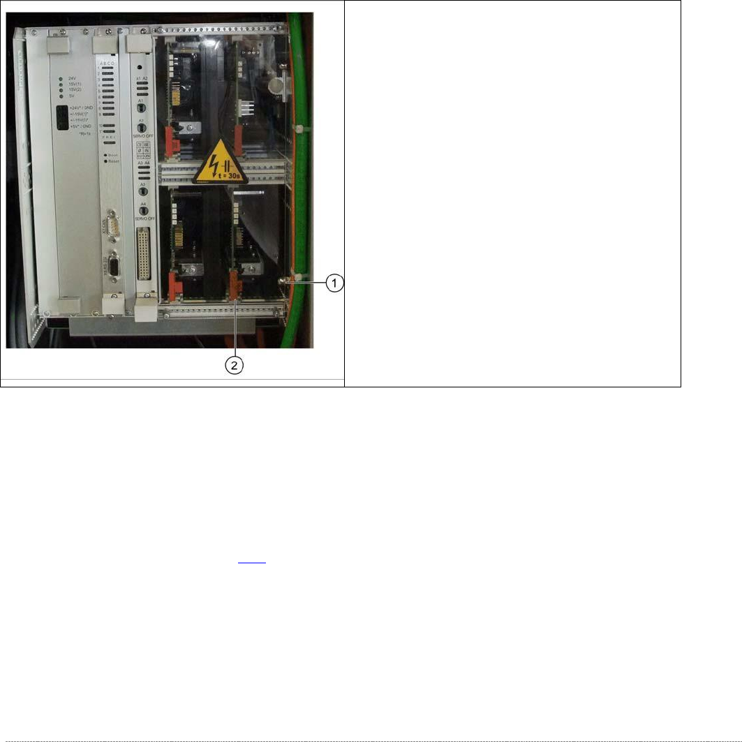
➢ Loosen and remove the lower cap nut on the
slot unit (1).
➢ Loosen the counternut and pull the screw out
towards the back until you can remove the
servo amplifier.
➢ Press the lock under the board of the servo
amplifier (2).
➢ Carefully pull the servo amplifier out of the
control unit.
➢ Carefully insert the new servo amplifier.
➢ Make sure that the servo amplifier engages
properly.
➢ Tighten the cap nut and counternut.
➢ Refit the plexiglass cover and screw into place.

Service Manual WPC5 / WPC6
Page 3-53
3.6.3.7 Replace the Ballast Circuit
Spare Part
• Ballast circuit LZS200/1000 [00344207-xx]
Removal / Installation
➢ Wear the ESD wristband.
➢ Loosen the 4 screws fastening the plexiglass cover and remove this.
➢ Press down the lock on the ballast circuit (see "3.6.3 Control Unit" [➙
3-47]).
➢ Carefully pull the ballast circuit out of the control unit.
➢ Carefully insert the new ballast circuit.
➢ Make sure that the ballast circuit engages properly.
➢ Refit the plexiglass cover and screw into place.
Settings
• No settings are required.
NOTICE
Ballast circuit with integrated micro fuse
There is a micro fuse T 10A/440V on the ballast circuit.
Check this fuse for continuity with the help of a digital multimeter and replace if
necessary.
NOTICE
Braking resistor for lifting axis
The braking resistor for the lifting axis is 12 Ohm +- 10%
This can be measured on the back plane. To do this, first make sure that the WPC is
switched off and then remove the ballast card and the servo card for the feed axis.
Service Manual WPC5 / WPC6
Page 3-54
3.6.3.8 Replace the Complete Control Unit
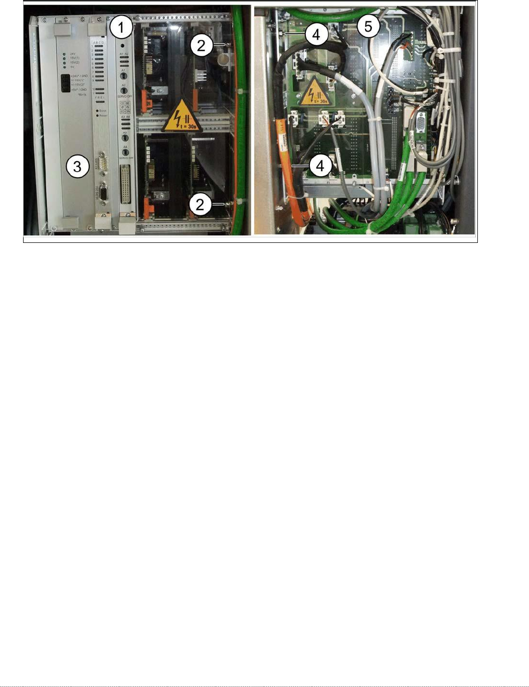
Overview – Example of WPC6
1. Control unit – front
2. 2 x cap nuts on the front
3. CAN bus connection on controller board
4. 2 x nut on the back
5.
Control unit – back plane with plexiglass cover
Spare Part
• WPC5 control unit assembly [03072950-xx]
• WPC6 control unit assembly [03056855-xx]
Removal
➢ Wear the ESD wristband.
➢ Loosen the 4 screws fastening the plexiglass cover (5) to the back plane and remove this.
➢ Check whether all cables are labeled.
➢ Make sure that you are able to correctly assign all cables and plugs again. Where necessary,
label cables, plugs and connections for easier reconnection later.
➢ Unplug the CAN bus cable from the front of the controller board..