00196624-04_Service Manual WPC5_6_EN_01-2019.pdf - 第54页
Service Manua l WPC5 / WPC6 Page 3- 54 3.6.3.8 Repla ce the Co mplete Contro l Unit Overview – Exa mple of WPC6 1. Co ntro l unit – fr ont 2. 2 x ca p nuts on the fron t 3. C AN bus conn ection on c ontrol ler bo ar d …

Service Manual WPC5 / WPC6
Page 3-53
3.6.3.7 Replace the Ballast Circuit
Spare Part
• Ballast circuit LZS200/1000 [00344207-xx]
Removal / Installation
➢ Wear the ESD wristband.
➢ Loosen the 4 screws fastening the plexiglass cover and remove this.
➢ Press down the lock on the ballast circuit (see "3.6.3 Control Unit" [➙
3-47]).
➢ Carefully pull the ballast circuit out of the control unit.
➢ Carefully insert the new ballast circuit.
➢ Make sure that the ballast circuit engages properly.
➢ Refit the plexiglass cover and screw into place.
Settings
• No settings are required.
NOTICE
Ballast circuit with integrated micro fuse
There is a micro fuse T 10A/440V on the ballast circuit.
Check this fuse for continuity with the help of a digital multimeter and replace if
necessary.
NOTICE
Braking resistor for lifting axis
The braking resistor for the lifting axis is 12 Ohm +- 10%
This can be measured on the back plane. To do this, first make sure that the WPC is
switched off and then remove the ballast card and the servo card for the feed axis.
Service Manual WPC5 / WPC6
Page 3-54
3.6.3.8 Replace the Complete Control Unit
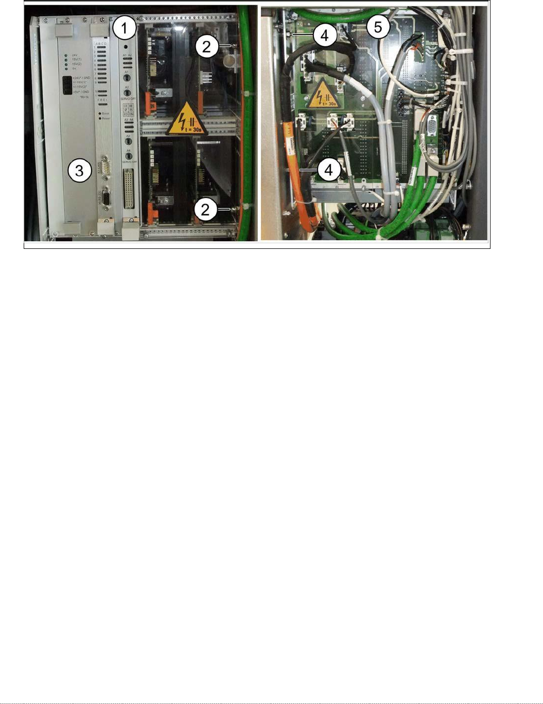
Overview – Example of WPC6
1. Control unit – front
2. 2 x cap nuts on the front
3. CAN bus connection on controller board
4. 2 x nut on the back
5.
Control unit – back plane with plexiglass cover
Spare Part
• WPC5 control unit assembly [03072950-xx]
• WPC6 control unit assembly [03056855-xx]
Removal
➢ Wear the ESD wristband.
➢ Loosen the 4 screws fastening the plexiglass cover (5) to the back plane and remove this.
➢ Check whether all cables are labeled.
➢ Make sure that you are able to correctly assign all cables and plugs again. Where necessary,
label cables, plugs and connections for easier reconnection later.
➢ Unplug the CAN bus cable from the front of the controller board..
Service Manual WPC5 / WPC6
Page 3-55
Installation
➢ During installation, make sure you fit the parts in the correct position (front/back).
➢ Carefully lift the new control unit onto the threaded pins and fix in place with the 4 nuts.
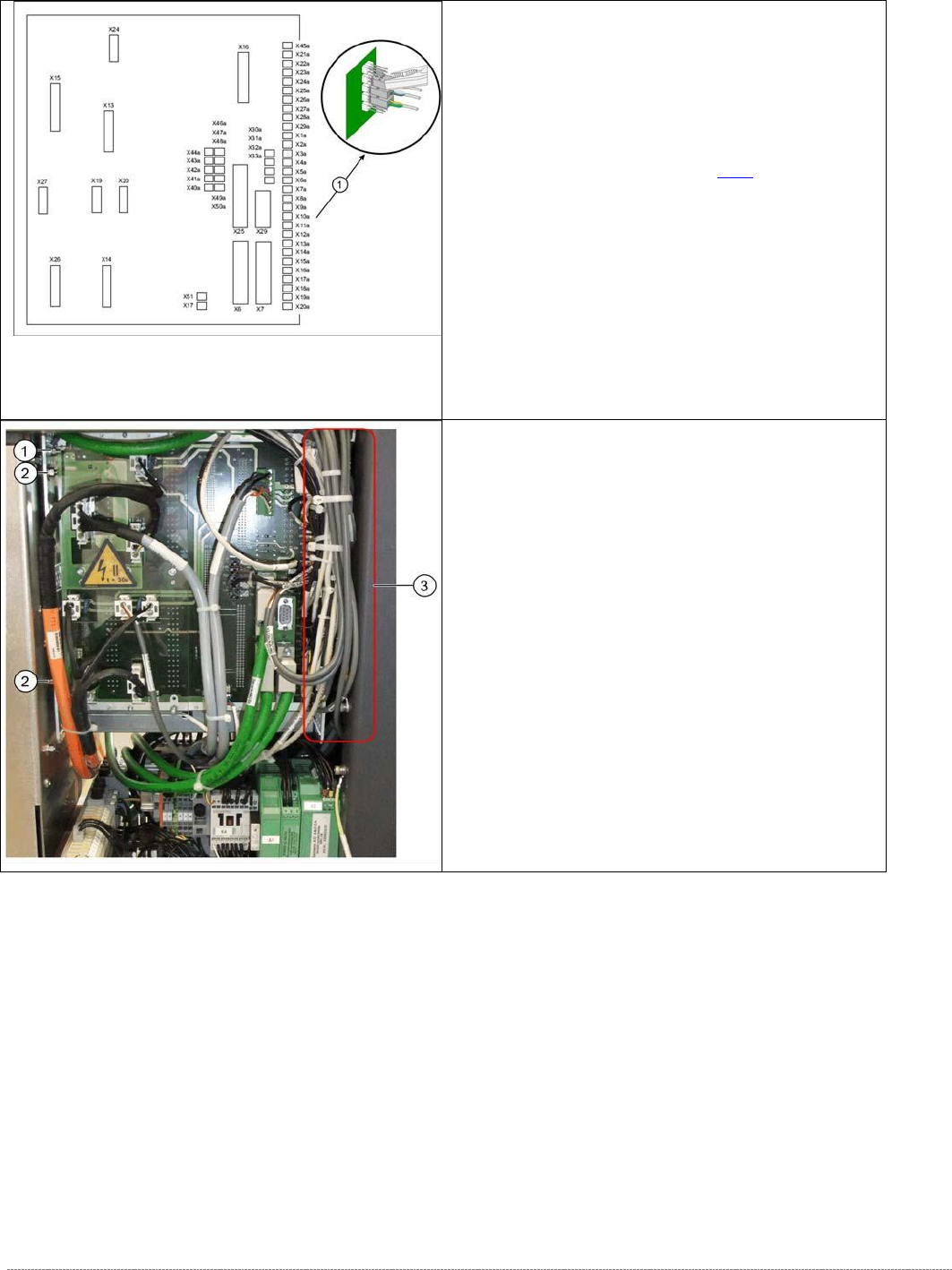
➢ Restore all electrical connections and plug in the ground cable (1) again.
➢ Run the cables neatly inside the control unit (3) so that they do not interfere with any other
parts.
➢ Fasten the cable with cable ties.
➢ Fit the plexiglass cover..
Control unit back plane - details
1. Connections for limit switches, sensors and light
barriers.
For a detailed overview of the connections, see
"3.7.1.3 Detailed Connections for Limit Switches,
Sensors and Light Barriers" [➙
3-71].
➢ Carefully unplug connections X1A to X20A on
the terminal strip (proximity switch, sensors etc.)
with a suitable pair of pliers (e.g. combination
pliers) (1). Make sure that you do not bend the
contact pins.
➢ Unplug the remaining cables, plugs and
connections.
Control unit back side – example WPC6
➢ Disconnect the control unit ground cable (1)
from the WPC frame.
➢ Loosen the two nuts (2) from the threaded pins
on the control unit located on the back plane
side.
➢ Loosen the two cap nuts from the threaded pins
on the front side of the control unit.
➢ Carefully pull the control unit out towards the
front.