00196624-04_Service Manual WPC5_6_EN_01-2019.pdf - 第59页
Service Manua l WPC5 / WPC6 Page 3- 59 3.6.4 Overview of Electrical Components 3.6.4.1 Back P lane Back view – Ove rview Legend 1. Conn ections for limit switch es, sensors and light barri ers 2. Fan c onnection For a …

Service Manual WPC5 / WPC6
Page 3-58
➢ Lever the mounting frame (2) out of the control unit holes with a suitable tool (e.g.
screwdriver).
➢ Remove the mounting frame with fan.
➢ Mark the installation position of the fan (1) in the mounting frame. Make a note of the
direction in which air is blown out! The fan takes in air from below and blows it into the inside
of the control unit.
➢ Loosen the 4 screws (5) fastening the fan (1) to the mounting frame.
➢ Remove the fan.
Installation
➢ Fit the fan in the mounting frame. Note the position of the connection cable.
➢ Carefully lever the mounting frame with its openings into the holes.
➢ Fit the mounting frame with the fan in the control unit.
➢ Tighten the two screws (6) on the control unit and reconnect to the power supply.
➢ Fit the complete control unit (see "3.6.3.8 Replace the Complete Control Unit" [➙
3-54]).
Settings
➢ Check the flow of air from the fan. The fan takes in air from below and blows it into the
inside of the control unit.
Service Manual WPC5 / WPC6
Page 3-59
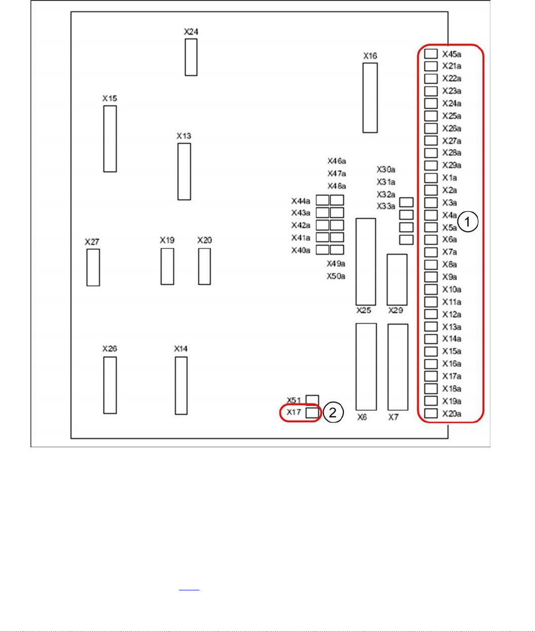
3.6.4 Overview of Electrical Components
3.6.4.1 Back Plane
Back view – Overview
Legend
1. Connections for limit switches, sensors and light barriers
2. Fan connection
For a detailed overview of the connections, see "3.7.1.3 Detailed Connections for Limit Switches,
Sensors and Light Barriers" [➙
3-71].
Service Manual WPC5 / WPC6
Page 3-60
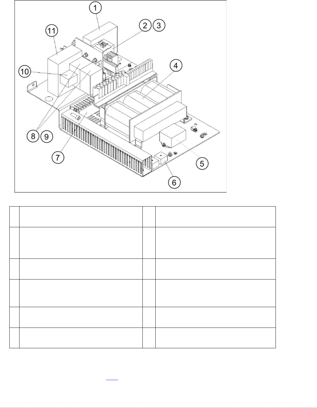
3.6.4.2 Power supply WPC5
1
Inrush current limitation board WPC
[03047752-xx]
7
Cable duct 40X40mm GYT1-40X40
[03008823-xx]
2
Contactor 3RT10 15-2BM42 [03048357-xx]
discontinued,
Contact. 3RT2 AC3 1NC DC220V 3p
[03171139-xx] successor, K4
8
Contactor 3RT10 15-1BB42 [03048563-
xx] discontinued
,
Contactor 3RT2 AC3 1NC DC24V 3p
[03171138-xx] successor, K2 and K3
3
Suppression diode for contactors DC150-
250V [03048925-xx]
9
Suppression diode for contactors DC 24-
70V [00342396S01]
4
Transformer WPC5 [03057556-xx]
10
Auxil. switch block 3RH19 / 2 POL 1Ö+1S
[03048564-xx] discontinued,
Auxiliary switch block 3RH2 1NC + 1NO
[03171137-xx] successor; on K3
5
Line filter for 3-phase system 10A
[03048582-xx]
11
Emergency stop switchgear 3TK2828-
1BB41 [00372649-xx], K1
6
Rectifier bridge 800V / 25A [03048868-xx]
For a detailed overview of the connections, see "3.7.1.3 Detailed Connections for Limit Switches,
Sensors and Light Barriers" [➙
3-71].