00196624-04_Service Manual WPC5_6_EN_01-2019.pdf - 第71页
Service Manua l WPC5 / WPC6 Page 3- 71 3.7.1.3 Deta iled Conne ctions f or Limit Switche s, Sen sors and L ight Ba rriers 3.7.1.3.1 WPC5 Serien-Nr . < 3xxx: WPC5- Elektrics; Serien -Nr.: < 3x xx
Service Manual WPC5 / WPC6
Page 3-70
3.7.1.2 General Installation/Removal Instructions
Tools and Equipment Required
• Standard tool
• Cable ties
• For a detailed overview of the connections, see "3.7.1.3 Detailed Connections for Limit
Switches, Sensors and Light Barriers" [
➙
3-71].
Cable routing
The cables are fixed and collected together with cable ties. Remove any cable ties which you do
not need with suitable wire cutters. Note how the cables are run and the position of the cable ties.
Fix new cable ties in the same positions as the old ones.
Some cables will be fixed with cable clamps which are held by a socket-head screw. Note how
the cables are run and fit the cable clamps with the socket-head screw in the same positions as
they were before.
CAUTION
Take care not to damage the cables!
Make sure that the cables do rub against any parts and that they are not pinched or damaged
when the lifting and feed axes move..
➢ Make sure that the cables are fixed with cable ties and/or clamps.
➢
Make sure that the cables do not rub against any parts and are not pinched when the lifting
and feed axes move.
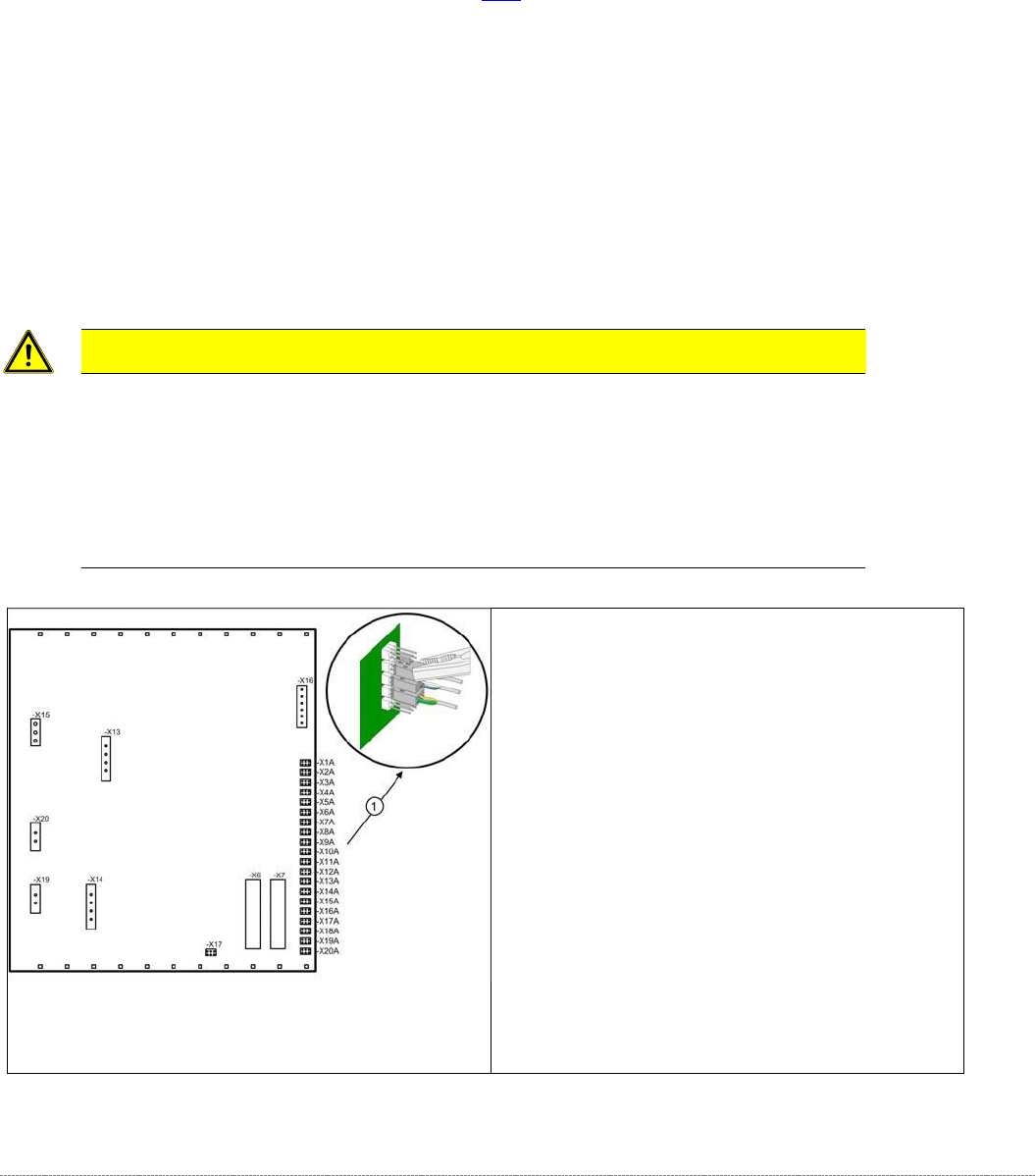
Note the terminal assignment
All sensor cables lead to the back plane of the
control unit and are connected to the right-hand
terminal strip there - X1a to X13a (1) .
➢ Check whether all cables are labeled.
➢ Make sure that you are able to correctly assign
all cables and plugs again. Where necessary,
label cables, plugs and connections for easier
reconnection later.
➢ Carefully disconnect the required connections
from the relevant terminal (1) with a suitable
pair of pliers (e.g. combination pliers). Make
sure that you do not bend the contact pins.
Service Manual WPC5 / WPC6
Page 3-71
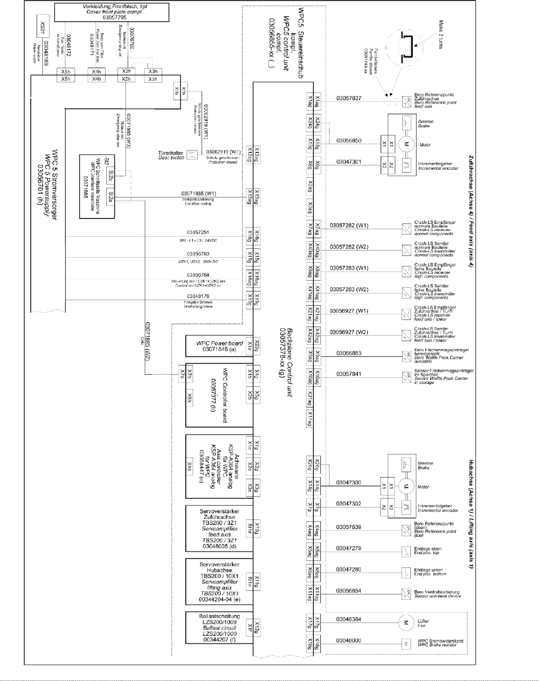
3.7.1.3 Detailed Connections for Limit Switches, Sensors and Light Barriers
3.7.1.3.1 WPC5 Serien-Nr. < 3xxx:
WPC5- Elektrics; Serien-Nr.: < 3xxx
Service Manual WPC5 / WPC6
Page 3-72
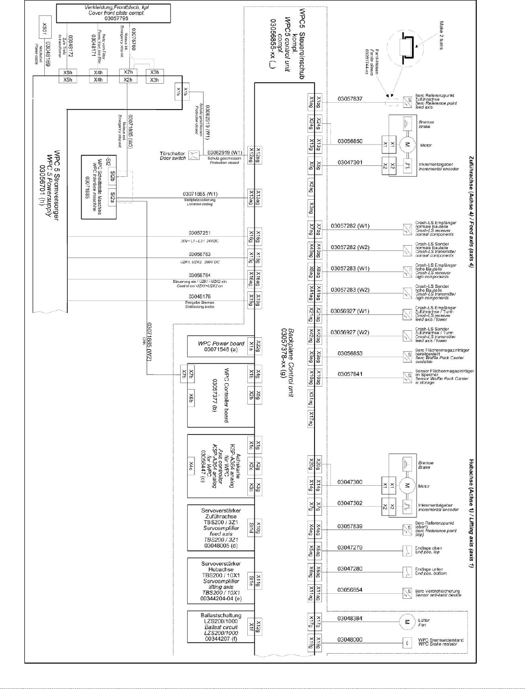
3.7.1.3.2 WPC6 Serien-Nr. < 3xxx:
WPC6 – Elektrics_1;
Serien-Nr.: < 3xxx