00196624-04_Service Manual WPC5_6_EN_01-2019.pdf - 第99页
Service Manua l WPC5 / WPC6 Page 3- 99 3.7.12 Sensor 12 Reference Proximity S witch Load axis Spare Part • Reference point prox imity switch load axis [03056947- xx] Removal / Install ation ➢ Loosen the two screws ( 1)…
Service Manual WPC5 / WPC6
Page 3-98
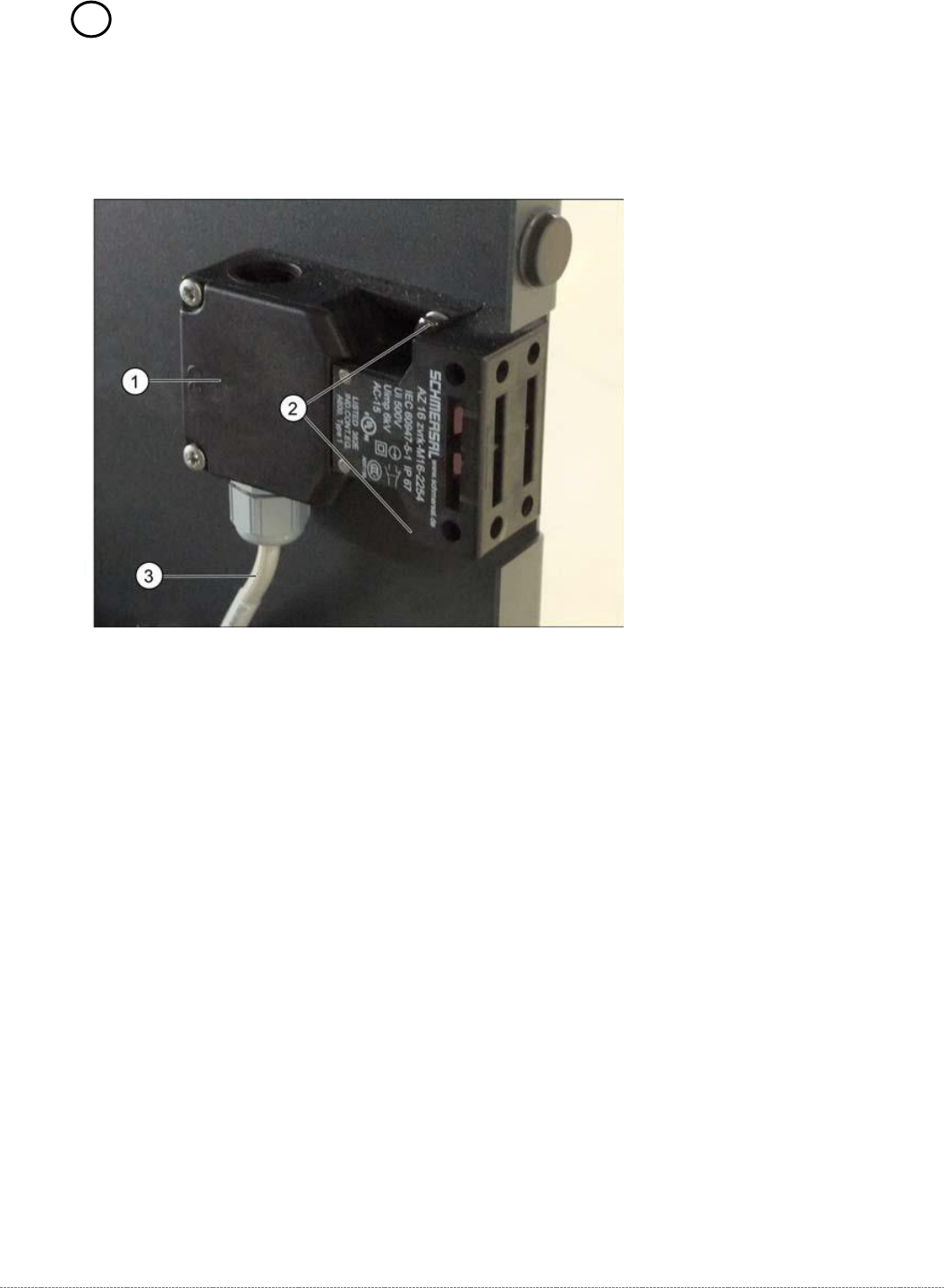
3.7.11 13 Safety Switch
Spare Part
• Safety switch, closed (safety switch with cable) [03062919-xx]
Removal / Installation
➢ Mark the installation position of the safety switch (1) at the two fastening screws (2) with
slots.
➢ Loosen the two fastening screws (2) and remove the safety switch (1).
➢ Unthread the connection cable (3) as far as the control unit back plane..
The connection cable has two separate connections:
• Unplug the connection cable at terminal strip x12a on the control unit back plane.
• Unplug the connection cable from the safety loop.
➢ Fit the new safety switch at the marked installation position.
➢ Restore the electrical connection and fix the connection cable into place.
Settings
➢ Make sure that the door contact engages properly. If necessary, correct the installation
position at the slots.
➢ Check that the safety switch switches reliably at the docked WPC.
Service Manual WPC5 / WPC6
Page 3-99
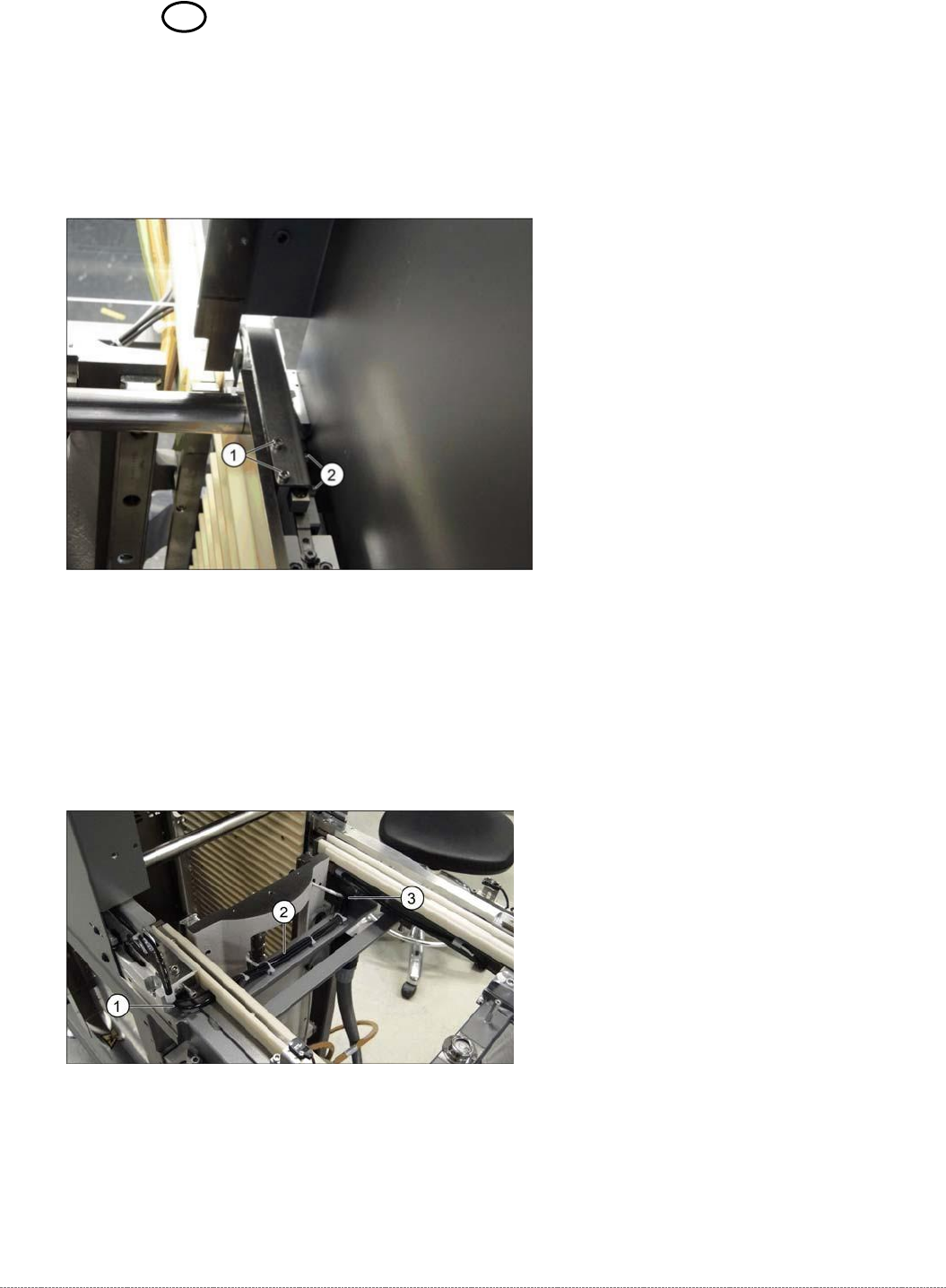
3.7.12 Sensor 12 Reference Proximity Switch Load axis
Spare Part
• Reference point proximity switch load axis [03056947-xx]
Removal / Installation
➢ Loosen the two screws (1) fastening the sensor fixture bracket and unthread the cable.
➢ Unthread the connection cable as far as the control unit back plane and unplug it from the
terminal strip.
➢ Loosen the two screws (2) fastening the sensor to the fixture bracket and then remove the
sensor.
➢ Screw the new sensor to the fixture bracket (2).
➢ Fix the bracket into the tower with the two screws which you removed (1).
➢ Run the cable out of the tower, under the feed axis and along to the other side (1 to 3) and
up to the back plane of the control unit. Fix the cable into place with cable ties.
➢ Restore the electrical connection and fix the connection cable into place.

Service Manual WPC5 / WPC6
Page 3-100
Settings
➢ Check the function and correct position of the reference sensor. The sensor must trigger
when the driver actuator is just below the sensor. (Reference point).
➢ To do this, open the station software menu
⇨ Sensors and Functions ⇨ Location ⇨ Check functions for WPC ⇨ Advanced functions
.
➢ Enable the feed axis and click on the
Reference bero
button.
The feed axis will be moved so that the driver actuator triggers the reference sensor. The
reference point will be calculated.
The calculated value will be shown and can then be saved with the
Commit
button.
➢ If an error message appears, correct the mechanical position by adjusting the cam on the
driver (see "4.3.3.1 Setting the Driver Cam" [➙
4-135]) and repeat the measuring process.
➢ Coat the cam fastening screw with locking varnish.
➢ Calibrate the reference proximity switch (see "4.2.3 Reference Proximity Switch (Bero)" [➙
4-126]).