182049 Viking Installation Manual - 第16页
semi automatic SAFETY FEA TURES HIGH VOLTAGE PROTEC TION 2.6 Installatio n Manual Chapt er Issue 1 O ct 02

semi automatic
SAFETY FEATURES
HIGH VOLTAGE PROTECTION
Chapter Issue 1 Oct 02 Installation Manual 2.5
HIGH VOLTAGE PROTECTION
Mechanisms The machine incorporates Class 1 electrical protection according to the IEC 536
requirement 1:1993.
All machines prior to shipment undergo electrical safety tests as described in
EN60204-1 (1997) Section 19:
• 19.2 Continuity of the protective bonding circuit
• 19.3 Insulation resistance test
With the exception of the optional Onboard Suction Filtration Unit, machine
mechanisms are powered by voltages less than 50V.
NOTE
Refer to Machine Preparation chapter (Machine Relocation section) for infor-
mation on Vacuum Filtration Unit checks.
Access Where incoming supply voltages are present, protection is afforded by control-
ling access to the enclosures that house the supply. The machine is fitted with
a mains isolator switch that cuts power to all circuits located beyond the switch
on both incoming and outgoing power terminals. The isolator switch is located
at the front of the machine.
Hazard Warning
Labels
Hazard warning labels are placed on the outside of enclosures where danger-
ous voltage (100V-240V) terminations are present within.
Earth Bonding All external metal surfaces are mechanically and electrically bonded to the
machine earth point. The bonding wire used is identified by its green and yellow
insulation and is commonly used to earth bond throughout. Care should be
taken when removing these links that when they are replaced they are secured
tightly and cleanly.

semi automatic
SAFETY FEATURES
HIGH VOLTAGE PROTECTION
2.6 Installation Manual Chapter Issue 1 Oct 02
semi automatic
SERVICES REQUIRED
MACHINE EXTERNAL SERVICES
Chapter Issue 1 Oct 02 Installation Manual 3.1
CHAPTER 3 SERVICES REQUIRED
MACHINE EXTERNAL SERVICES
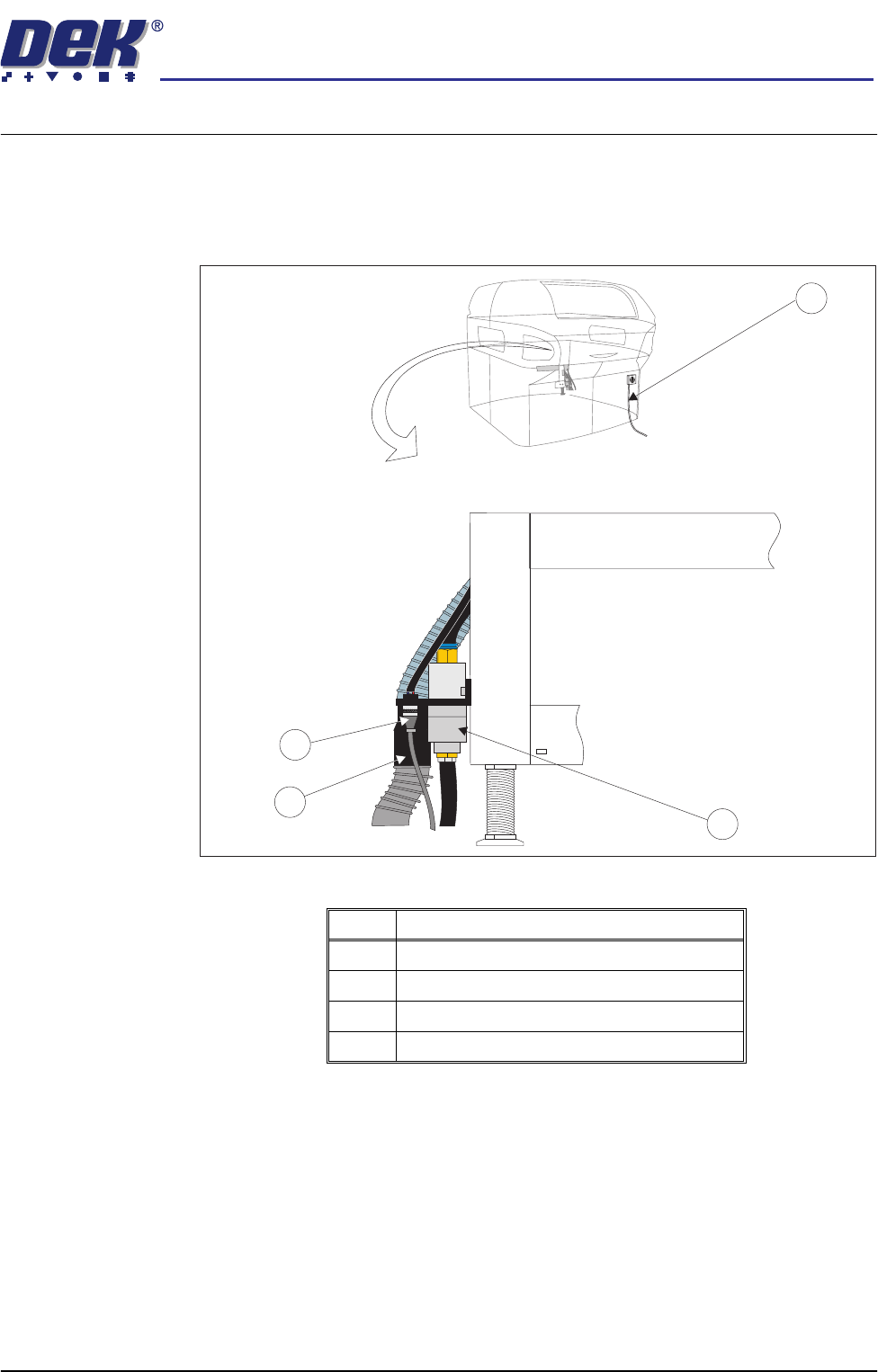
In order for the machine to function correctly the following services must be
available. The services must be stable and clean.
Figure 3-1 External Services
No Description
1 Mains Supply
2 Air Connection
3 Vacuum Connection
4 24V Vacuum Control
1
3
4
2