182049 Viking Installation Manual - 第29页
semi automatic MACHI NE PREPARAT ION TRANSIT BRA CKETS Chapter Issue 1 Oct 02 Instal lation Manual 5.3 Figure 5-1 T ransit Bracket Location Item Description Item De s cription 1 Y Actuator Cla mp 6 Print Carriage S top (…

semi automatic
MACHINE PREPARATION
TRANSIT BRACKETS
5.2 Installation Manual Chapter Issue 1 Oct 02
TRANSIT BRACKETS
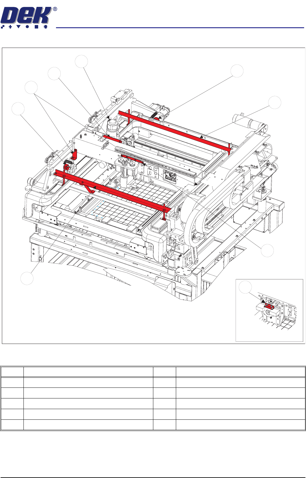
Locations In order to prevent major machine assembly movement during transportation,
eight transit brackets are fitted to the machine, a description of each is detailed
in the table below.
Bracket Name Purpose
Front Transit Bracket
Secures the front of the screen chase, print-
head assembly, printhead lift and the squee-
gee mounts
X Axis Fwd Actuator Restrainer Bracket Prevents the screen chase colliding with the
forward X axis actuator
Print Carriage Stops (in 2 positions) Secures either end of the print carriage to the
print head assembly
Squeegee/ProFlow Transit Bracket Clamps the squeegee/ProFlow printhead
mechanism to the print carriage
Paste Dispense Transit Bracket Secure the optional paste dispense unit
X Axis Rear Actuator Restrainer Bracket Prevents the screen chase colliding with the
rear X axis actuator
Rear Transit Bracket Secures the rear of the screen chase
Y Axis Actuator Restrainer Bracket Prevents the screen chase colliding with the
rear Y axis actuator
semi automatic
MACHINE PREPARATION
TRANSIT BRACKETS
Chapter Issue 1 Oct 02 Installation Manual 5.3
Figure 5-1 Transit Bracket Location
Item Description Item Description
1 Y Actuator Clamp 6 Print Carriage Stop (Left & Right)
2 Rear Transit Bracket 7 Paste Dispense Transit Bracket
3 Squeegee Transit Bracket 8 Rear X Actuator Clamp
4 Front Transit Bracket 9 ProFlow Transit Bracket
5 Forward X Actuator Clamp
1
5
6
7
8
4
2
3
ProFlow Option
9
semi automatic
MACHINE PREPARATION
REMOVAL PROCEDURES
5.4 Installation Manual Chapter Issue 1 Oct 02
REMOVAL PROCEDURES
To remove the transit brackets from the machine, refer to the following proce-
dures:
Front Transit Bracket
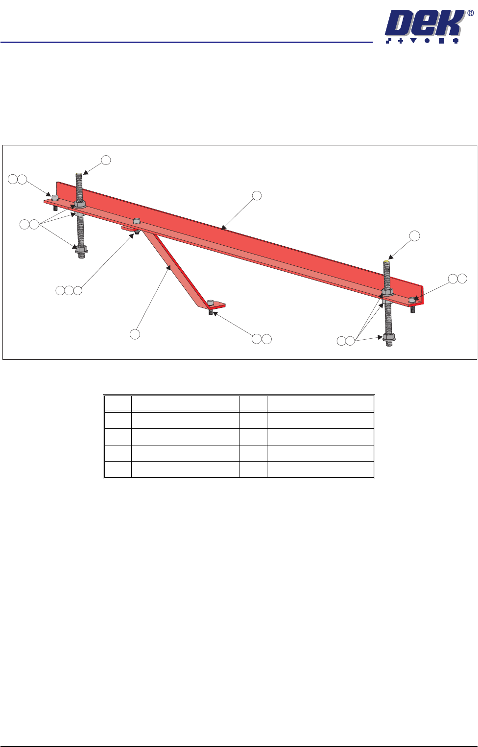
Figure 5-2 Front Transit Bracket (With Camera Bracket Fitted)
1. Remove the M5 cap head screw (Item 3) and washer (Item 8) securing the
camera transit bracket (Item 6) to the camera carriage. Loosen the M5 cap
head screw and nut at the top of the camera transit bracket and rotate the
bracket clear of the camera X axis timing belt.
2. On each of the M8 studs (Item 2), loosen the nuts and washers (Items 5 and
4) either side of the transit bracket, loosen the M8 nuts (Item 5) securing the
M8 studs (Item 2) to the screen chase. Unscrew the studs (Item 2) from the
screen chase.
3. Unscrew the two M5 cap head screws (Item 3) securing the front transit
bracket to the printhead.
4. Remove the front transit bracket.
Item Description Item Description
1 Front Transit Bracket 5 M8 Nut
2 M8 Stud 6 Camera Transit Bracket
3 M5 Cap Head Screw 7 M5 Ni-Loc Nut
4 M8 Washer 8 M5 Washer
3
1
6
2
2
8
8
3
7
8
3
3
8
4
5
4
5