182049 Viking Installation Manual - 第36页
semi automatic MACHI NE PREPARAT ION REMOVAL PR OCEDURES 5.10 Instal lation Manual Chapter Issue 1 Oct 02 ProFlow T ransit Bracket (if fitt ed) Figure 5-8 ProFlow T r ansit Bracket 1. Remove the two M5 cap head screws an…
semi automatic
MACHINE PREPARATION
REMOVAL PROCEDURES
Chapter Issue 1 Oct 02 Installation Manual 5.9
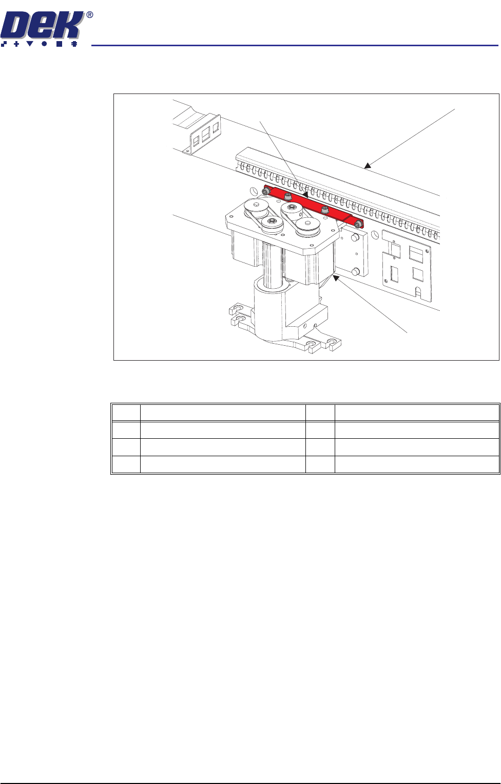
Squeegee Transit Bracket
Figure 5-7 Squeegee Transit Bracket
1. Whilst supporting the squeegee mounting assembly (Item 5), remove the
two M5 cap head screws and M5 washers (Items 1 and 2) securing the
squeegee transit bracket (Item 3) to the squeegee mounting assembly (Item
5).
2. Remove the two M5 cap head screws and M5 washers (Items 1 and 2)
securing the squeegee transit bracket (Item 3) to the print carriage (Item 4).
3. Remove the squeegee transit bracket (Item 3).
Item Description Item Description
1 M5 Cap Head Screw 4 Print Carriage
2 M5 Washer 5 Squeegee Mounting Assembly
3 Squeegee Transit Bracket
Print Carriage
Squeegee
Mounting Assembly
Squeegee Transit
Bracket
semi automatic
MACHINE PREPARATION
REMOVAL PROCEDURES
5.10 Installation Manual Chapter Issue 1 Oct 02
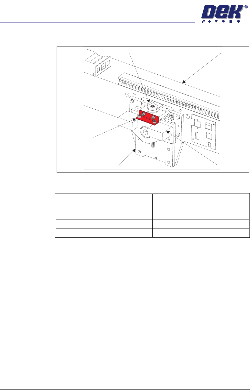
ProFlow Transit Bracket (if fitted)
Figure 5-8 ProFlow Transit Bracket
1. Remove the two M5 cap head screws and M5 washers (Items 3 and 4)
securing the ProFlow transit bracket (Item 7) to the bearing block (Item 5).
2. Remove the two M5 cap head screws and M5 washers (Items 3 and 4)
securing the ProFlow transit bracket (Item 7) to the motor support plate
(Item 1).
3. Remove the ProFlow transit bracket (Item 7).
This concludes the transit bracket removal procedure. Transit brackets and
associated fasteners should be stored for future reuse.
Item Description Item Description
1 Motor Support Plate 5 Bearing Block
2 Print Carriage 6 ProFlow Mounting Assembly
3 M5 Cap Head Screw 7 ProFlow Transit Bracket
4 M5 Washer
Print Carriage
ProFlow Mounting Assembly
ProFlow Transit
Bracket
Motor Support Plate
Bearing Block
semi automatic
MACHINE PREPARATION
MACHINE RELOCATION
Chapter Issue 1 Oct 02 Installation Manual 5.11
MACHINE RELOCATION
General In the event of machine relocation, refer to the Technical Reference Manual,
Transportation chapter for transit bracket fitment procedure.
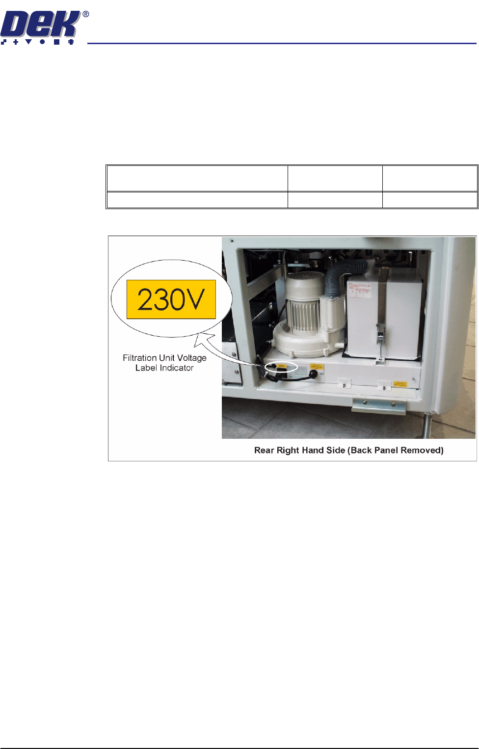
Voltage Supply If a machine specified for a low voltage factory supply area is re-located to a
high voltage factory supply area, or vice versa, the following check is required:
Figure 5-9 Optional Filtration Unit - Voltage Check
Fitted Option Low Voltage Unit
(110V)
High Voltage Unit
(230V)
Vacuum Filtration Unit