182049 Viking Installation Manual - 第39页
semi automatic MACHI NE PREPARAT ION MACHI NE ASSEMBLY Chapter Issue 1 Oct 02 Instal lation Manual 5. 1 3 MACHINE ASSEMBL Y Assemble the machine component s and assemblies removed for transpo rtation to the machine, as l…

semi automatic
MACHINE PREPARATION
MACHINE RELOCATION
5.12 Installation Manual Chapter Issue 1 Oct 02
Vacuum Filtration
Unit Option
In accordance with customer requirements, the optional onboard vacuum filtra-
tion unit is fitted to the machine in one of two configurations:
• 110 Volt Unit
• 230 Volt Unit
CAUTION
LOW VOLTAGE FILTRATION UNIT.
Filtration unit internal fuse (8A) is liable
to rupture if low voltage unit is connected to a high voltage factory supply.
110 Volt Unit If the printing machine is reconfigured from a low voltage factory supply setting,
to that of a higher voltage setting. The low volt optional vacuum filtration unit
(DEK Part No. 163557), must be replaced with a high voltage unit (Dek Part
No.163558).
NOTE
No apparent damage to the unit would occur, with the exception of the supply
cable temperature increasing and consequent rupturing of the unit internal fuse
(10A).
230 Volt Unit If the printing machine is reconfigured from a high voltage factory supply setting,
to a lower voltage setting. The high volt vacuum filtration unit must be replaced
with a low voltage unit.
NOTE
No apparent damage to the unit would occur, however the unit performance
would be greatly diminished.
semi automatic
MACHINE PREPARATION
MACHINE ASSEMBLY
Chapter Issue 1 Oct 02 Installation Manual 5.13
MACHINE ASSEMBLY
Assemble the machine components and assemblies removed for transportation
to the machine, as listed in the Machine Components table in the Unpacking
Instructions chapter of this manual.
Fitting of the
Transport Rail
Assembly
To fit the transport rail assembly, carry out the following procedure:
1. Remove the left hand machine side covers.
2. Ensuring the transport rail assembly is fully supported, attach it to the
machine lower frame attachment points using eight M5 bolts. DO NOT fully
tighten the bolts at this stage.
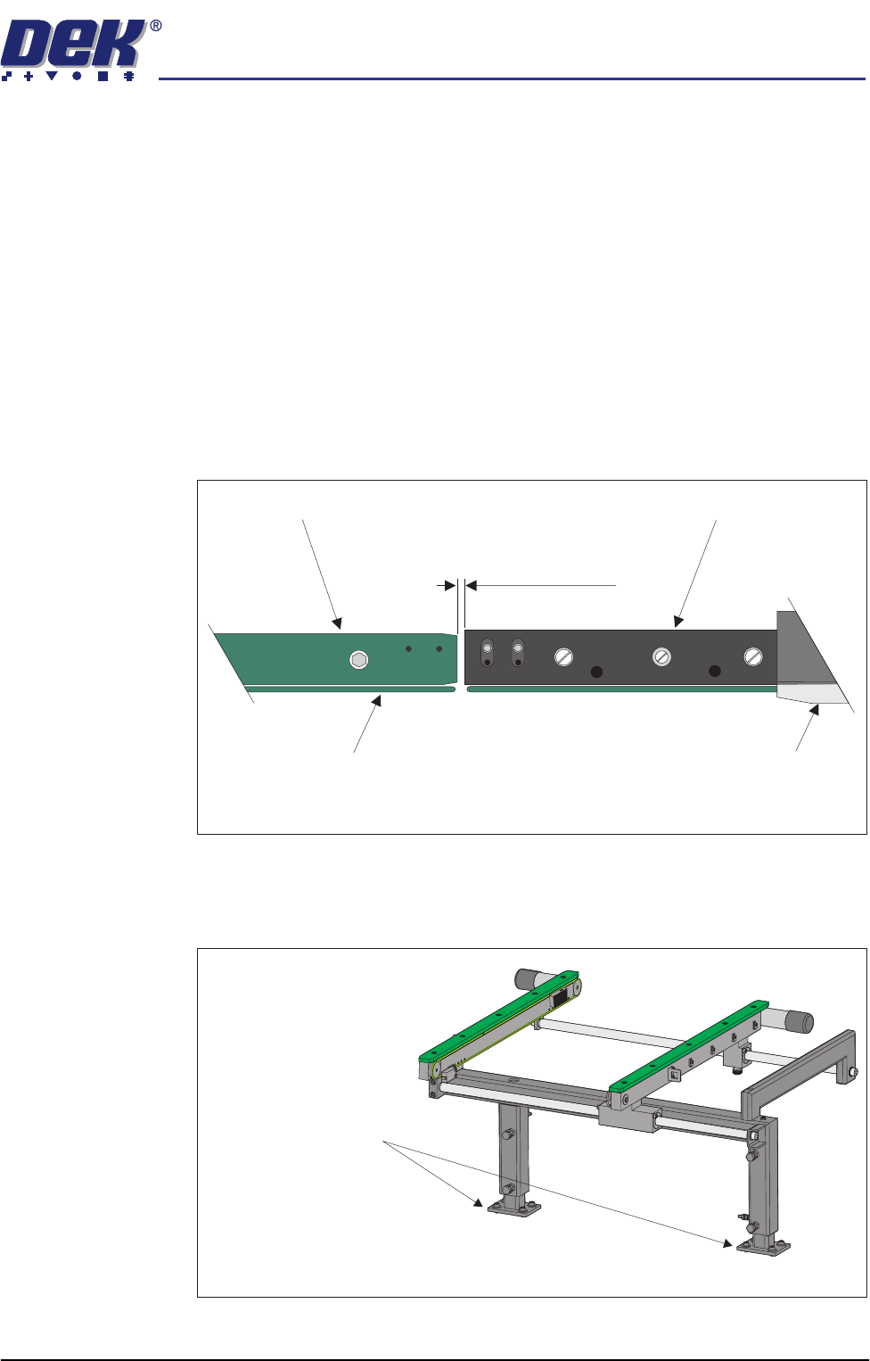
3. Carry out the following procedure to check the gap between the print station
rails and the transport rails:
a. Using feeler gauges or a 3mm allen key, ensure that the gap between the
print station and the transport rails (in two positions) is 3.0 ± 0.5mm.
b. If adjustment is required, carefully adjust the position of the transport rail
assembly to obtain the 3.0 ± 0.5mm gap.
c. Tighten the M5 securing bolts fitted in Step 2.
Board Clamp
Board Transport Belt
Transport Rail
Print Station Rail
Plan View on Print Station RailsTransport and
5157438
3.0mm +/- 0.5mm
Rear View of Transport Rail
Transport Rail Frame to
Machine Main Frame
(4 bolts in 2 positions)
semi automatic
MACHINE PREPARATION
MACHINE ASSEMBLY
5.14 Installation Manual Chapter Issue 1 Oct 02
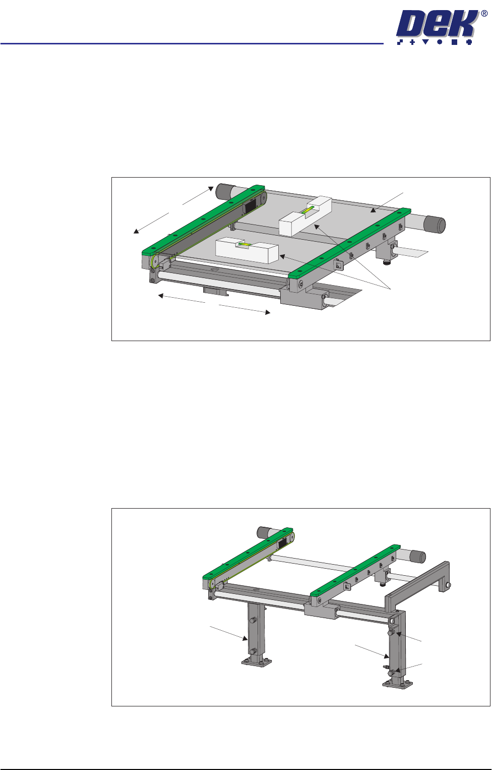
4. Carry out the following procedure to check and if required adjust the
transport rail levelling:
a. Adjust the transport rail width to approximately 250mm.
b. Place a Board Clamp Setting Plate Pt No 140403 onto the transport rail
belts.
c. Place a spirit level on top of the setting plate and check the levelness of
the rails in the X and Y planes.
d. If adjustment in the X plane is required, carry out Steps 4e - 4h.
e. Loosen the three hexagonal headed bolts, two on the inner face and one
on the outer face of the front upright of the transport rail frame.
f. Using the two hexagonal headed bolts on the inner face of the rear upright
of the transport rail frame, carefully loosen or tighten the bolts to level the
assembly.
NOTE
Tightening bolt A and loosening bolt B raises the inboard end of the
transport rails. Loosening bolt A and tightening bolt B lowers the inboard
end of the transport rails.
X
Y
Board Clamp Setting Plate
Spirit Level
View on Transport Rail
Bolt A
Bolt B
Rear Upright of the
Transport Rail
Front Upright of the
Transport Rail
Rear view of Transport Rail